I got Android code(QCM2290_Android12) from git file server from Quectel. I am able to compile and deploy but I hit the wall while making progress further as I am new to AOSP code. Some doubts:
- I was expecting QSSI to serve hardware specific things and UM to serve the top layer but they both have same folder afaik.
- Where are the main applications that end up being deployed on the SC200E later?
- Where to define which applications are built and deployed?
- How to define kiosk mode(single app in immersive mode) in the android code?
Hi,
In general, you can put your app into QSSI.12/packages/apps
I did make changes to launcher3 app’s search bar and those got reflected in the output on phone. But when I made changes to the Messaging app, they didn’t reflect(I changed the app name directly). Is there something like QSSI contains privileged apps and UM has the non privileged ones?
Can you please tell how to define the kiosk mode in the AOSP code?
HI,
What’s your requirement?
Do you want to use your own Launcher instead of the Launcher3?
I don’t want to change the launcher per se, I want to run a single kotlin app fullscreen at boot without the system bar and navigation bar.
Hi,
From your description, you need to use your app to replace Launcher3
So you need to remove Launcher3 and make your app as Launcher app.
If yes, I can provide a method to you, but you need to develop your own Launcher app
Hey,
Now I have an app that acts like launcher I think:
With androidmanifest.xml of app being:
<?xml version="1.0" encoding="utf-8"?>
<manifest xmlns:android="http://schemas.android.com/apk/res/android" xmlns:tools="http://schemas.android.com/tools">

    <application
        android:label="@string/app_name">
        <activity android:name=".MainActivity"
            android:noHistory="true"
            android:launchMode="singleTask"
            android:exported="true"
            android:theme="@style/Theme.AppCompat.Light.NoActionBar">
            <intent-filter>
                <action android:name="android.intent.action.MAIN" />
                <category android:name="android.intent.category.DEFAULT" />
                <category android:name="android.intent.category.HOME" />
            </intent-filter>
        </activity>
    </application>
</manifest>
But the status bar and navigation bar are still accessible which I don’t want. Also it would be great if after android logo at the very start leads directly to app being open rather than “Phone is starting…” . Am I doing custom launcher part right and what steps do I need to take further?
Hi,
If you don’t need status bar and navigation bar, I will provide patch to remove them.
For the phone tip, we can remove it. But the screen will keep show nothing for a while before entering your app.
You can consider if you want to remove the tip.
Thanks.
Hey,
Thanks, it would greatly help to remove status bar, navigation bar. About phone tip, I atleast need to disable the status bar, navigation bar that show during that time but with some customization of phone tip, it’s worth keeping in the application. Looking forward to making progress in this direction.
SC200E_A12_remove_statusbar_navigationbar.zip (3.5 KB)
You can apply this patch to remove statusbar&navigationbar.
1 Like
SC200E_A12_remove_phone_is_starting.zip (903 Bytes)
Apply this patch to remove the tip.
1 Like
Hey,
Thanks, it greatly helped to remove status bar, navigation bar. Moving forward I wanted to ask about access to UART and GPIOs through this type of app. I tried to use UsbManager(for UART access) which seems to not be made for this and I am not too sure which direction to go from here. Something along these lines: How to test the Main UART port of SC20 Module
Hi,
For GPIO and Uart, will provide apps and test steps to you.
Please wait for reply.
1 Like
Hey,
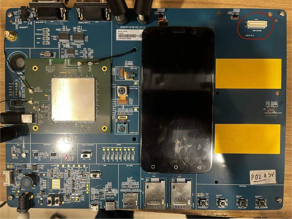
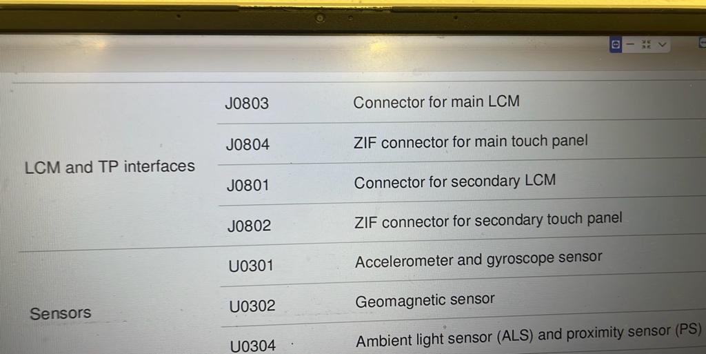
I also wonder if I can attach another screen of 10.5 inch MIPI connector type for testing purposes in below shown point?
HI,
For SC200E, there is one LCM interface
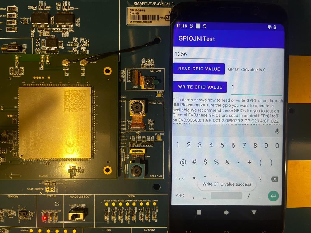
GPIOJNITest.zip (6.8 MB)
You can refer to this Android demo for GPIO.
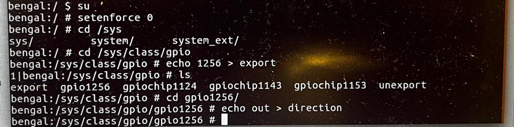
On SC200E, the GPIO offset is 1153.
Eg, if you want to operate GPIO112, the GPIO number should b3 1256(1153+112)
You can do as follows to export GPIO node.
adb shell
su
setenforce 0
cd /sys/class/gpio
echo 1256 > export
cd gpio1256
echo out > direction
1 Like
UartApp_optimize_20230614.zip (3.7 MB)
For uart app, you can refer to this demo.
You need to apply this patch to fix driver issue:
SC200E_A13_fix_uart_issue.zip (617 Bytes)
1 Like
Hey,
Thanks for the information on the LCM and GPIO. I have a doubt on GPIO aspect, I did same as you told but I was expecting one of 1-8 GPIO on evk to light up which didn’t happen:
I did try to do following steps hoping it would work but it didn’t, value file constantly has 0:
shell > chmod 0666 value
shell > echo 1 > value
shell > cat value
0
Hey,
Based on your previous answer, I infer that despite that EVB has 2 LCM interfaces, SC200E can only use one of them due to module limitations. But can I use the MIPI connector on top right on board as the secondary display?
Hey,
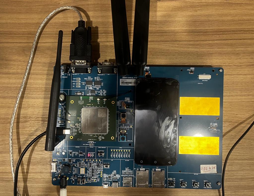
About the UART part, I am having issue too.
I have setup like below where the main UART(/dev/ttyHS1) is connected by RS-232-USB to my Ubuntu 16:
I am using program like below(when I put USB in /dev/ttyUSB0 only gets named hence its name for serial which I am doubtful about):
import serial
import threading
import time

# Function to continuously read from the serial port
def read_serial(ser):
    while True:
        data = ser.readline().decode('utf-8').strip()
        if data:
            print(f"Received: {data}")

# Configure the serial port settings
ser = serial.Serial('/dev/ttyUSB0', 115200)  # Replace with your specific serial port and baud rate

# Start a thread for reading serial data asynchronously
read_thread = threading.Thread(target=read_serial, args=(ser,))
read_thread.daemon = True
read_thread.start()

try:
    while True:
        print("Attempting to write!\n")
        # Write data to the serial port
        message = "Hello, Quectel!\n"  # Replace with the data you want to send
        ser.write(message.encode('utf-8'))  # Encode the string to bytes before sending

        # Add a brief sleep to avoid excessive writes
        time.sleep(1)
except KeyboardInterrupt:
    # Handle a KeyboardInterrupt (e.g., Ctrl+C) to gracefully exit the loop
    pass
finally:
    ser.close()  # Close the serial port when done
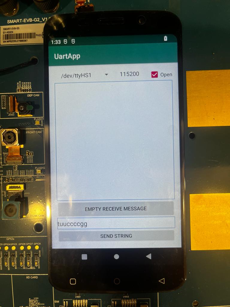
So when I run the script and open the UART app with below shown settings, I don’t receive and unable able to write much:
I keep getting nothing despite clicking send string multiple times:
Workstation:~/Desktop$ sudo python3.7 test.py
Attempting to write!

Attempting to write!

Attempting to write!

Attempting to write!
Additional info:
Workstation:~/Desktop$ ls /dev/tty*
/dev/tty    /dev/tty23  /dev/tty39  /dev/tty54      /dev/ttyS10  /dev/ttyS26
/dev/tty0   /dev/tty24  /dev/tty4   /dev/tty55      /dev/ttyS11  /dev/ttyS27
/dev/tty1   /dev/tty25  /dev/tty40  /dev/tty56      /dev/ttyS12  /dev/ttyS28
/dev/tty10  /dev/tty26  /dev/tty41  /dev/tty57      /dev/ttyS13  /dev/ttyS29
/dev/tty11  /dev/tty27  /dev/tty42  /dev/tty58      /dev/ttyS14  /dev/ttyS3
/dev/tty12  /dev/tty28  /dev/tty43  /dev/tty59      /dev/ttyS15  /dev/ttyS30
/dev/tty13  /dev/tty29  /dev/tty44  /dev/tty6       /dev/ttyS16  /dev/ttyS31
/dev/tty14  /dev/tty3   /dev/tty45  /dev/tty60      /dev/ttyS17  /dev/ttyS4
/dev/tty15  /dev/tty30  /dev/tty46  /dev/tty61      /dev/ttyS18  /dev/ttyS5
/dev/tty16  /dev/tty31  /dev/tty47  /dev/tty62      /dev/ttyS19  /dev/ttyS6
/dev/tty17  /dev/tty32  /dev/tty48  /dev/tty63      /dev/ttyS2   /dev/ttyS7
/dev/tty18  /dev/tty33  /dev/tty49  /dev/tty7       /dev/ttyS20  /dev/ttyS8
/dev/tty19  /dev/tty34  /dev/tty5   /dev/tty8       /dev/ttyS21  /dev/ttyS9
/dev/tty2   /dev/tty35  /dev/tty50  /dev/tty9       /dev/ttyS22  /dev/ttyUSB0
/dev/tty20  /dev/tty36  /dev/tty51  /dev/ttyprintk  /dev/ttyS23
/dev/tty21  /dev/tty37  /dev/tty52  /dev/ttyS0      /dev/ttyS24
/dev/tty22  /dev/tty38  /dev/tty53  /dev/ttyS1      /dev/ttyS25
Can you please tell what I am getting wrong? It would greatly help