Hi, I’m helping a client verify antenna performance on a board they’ve designed with two YC0017DA chip antennas. They’ve implemented the reference design matching circuit and (for the most part) PCB layout.
However, the return loss in the lower bands is not meeting the antenna datasheet return loss specs. I can measure good performance on the Quectel evb that does meet specs, though.
Is there any guidance on adjusting the matching network? What frequency bands or resonances are related to which components? I’d appreciate some guidance and methodology rather than just blindly going for trial and error.
thanks!
Hi radiogeek,
Do you have PCB layout and VSWR pictures?
Does the customer reserved the matching position and clearance area according to the reference design of YC0017DA?
What is the size of the PCB, and the antenna efficiency of different sizes is relatively different.
Did you test the actual antenna efficiency and not just the return loss? What is the efficiency of the low band? And I think it is normal if the efficiency of the low band is about 25%~30%. If the antenna efficiency meets the requirements, you don’t need to pursue the same return loss as the datasheet.
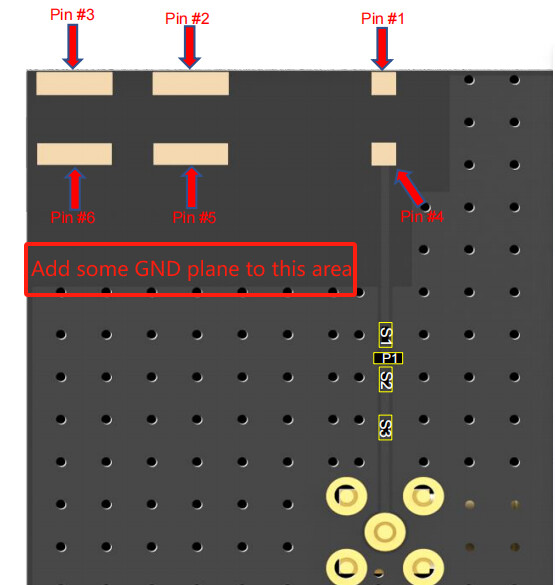
You can try to adjust the antenna match and modify the antenna clearance area.
For example:
Thanks @brown.du-Q for your quick help.
I can’t share pictures of the product due to confidentiality. But I can say that the entire board area is 12 cm x 12 cm and they did follow the recommended ground fill and keepout as you show in your picture.
They did not, however, add the stitching vias in the ground, which they will on the next revision.
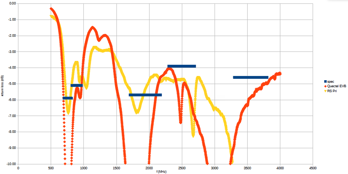
Here s a plot of return loss. The red trace is as measured on a Quectel evaluation board. The yellow is our board. And the blue lines are the datasheet specs for the various bands.
Unfortunately I do not have access to a proper antenna measurement chamber, so the best I can do now is to optimize the return loss and assume that radiated power follows.
thanks !
Hi Radiogeek,
-
The first your return loss is not too bad, and there is no frequency deviation. We don’t recommend the customer only pay attention to the return loss and ignore the antenna efficiency. In some cases, we found that the antenna efficiency can still reach 40% when the return loss is -3dB.
-
We suggest that it is necessary to combine the passive efficiency or TRP data of the antenna to judge whether the antenna can be used.
3.It is necessary to add vias to GND, which has a significant effect on the antenna.
4.There is no standard document on antenna matching to tell you how to debug, which requires extensive antenna debugging experience combined with Smith diagram to adjust the required band closer to 50 ohm.
Thanks !