Hi,
we are using the EC200S and BG95M4 modules, and want to use the FTM test mode for the correction of the insertion loss of cables and connectors used within our device.
It looks like we can use the FTM for this (AT+QRFTESTMODE, T+QRXFTM)
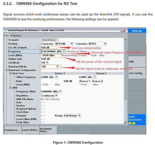
We want to avoid to get some expensive setup like an CW500 to generate a CW signal at a dedicated frequency, as describe for example here:
Is my understanding correct, that we could use any test equipment, which is able to generate a CW sine signal at 2+ GHz?
Best Regards,
Stefan
Hi @stefschu,
Yes, your understanding is correct. CMW is just an example of instrument which used to emit continuous waves.
Hi,
thanks for confirmation. We have used a “Rohde & Schwarz” SMBV100B Vector Signal Generator (8khZ .. 3 GHz) together with a BG95-M4. I have made one observation during RX testing I do not understand:
We set a continuous wave signal with the power of -60dBm.
The frequency setting I apply is according to the band/channel of the AT command entered.
e.g. LTE Band 8, channel 3625 has a DL-Frequency of 942.5 MHz.
We set the frequency at the signal generator to 942.5 MHz and get the following result:
AT+QRXFTM=1,“LTE BAND8”,3625,0,0,0
+QRXFTM: -623,-62
OK
If I change the frequency just 100kHz below or above, we get much better values.
For 942.4 MHz:
AT+QRXFTM=1,“LTE BAND8”,3625,0,0,0
+QRXFTM: -608,-60
OK
For 942.6 MHz:
AT+QRXFTM=1,“LTE BAND8”,3625,0,0,0
+QRXFTM: -608,-60
OK
Is our setup probably wrong? According to the image of the CMW500 setup (from the documentation of the EC200S) there has to be an offset of 500 kHz. Is probably the same offset required for the BG95-M4?
Best Regards,
Stefan
