RM520N-GL (R03A03) limited to MIMO rank 2 on n78 — ~40 Mbps vs 300 Mbps on handset, same cell

Hello,

I am running an RM520N-GL and seeing downlink throughput roughly 6–8x below what a commercial handset achieves on the same cell, same SIM, same location, at the same time. I have systematically eliminated the usual causes and would appreciate your input on what remains.

SETUP

  • Module: RM520N-GL
  • Firmware: RM520NGLAAR03A03M4G_A0.305.A0.305
  • Carrier board: 5G M.2 to Gigabit Ethernet (RTL8125 over PCIe, module in RC mode)
  • Host: Windows PC on the Ethernet port, bridge mode (MPDN_rule 0,1,0,1,1) — host holds the carrier WAN address directly, no NAT
  • MBN profile: ROW_Commercial (index 0, selected and activated)
  • APN configured, context active, IPv4v6

RADIO STATE (under sustained load)

  • EN-DC: AT+QENDC returns 1,1,0,1,0
  • Anchor: LTE B3, RSRP approx. -95 dBm, SINR 13–14 dB
  • NR SCC: n78, 100 MHz (bandwidth index 12), RSRP approx. -98 to -103 dBm, SINR 13–14 dB
  • AT+QRSRP shows four active NR receive chains: approx. -98 / -102 / -106 / -102 dBm
  • AT+QNWCFG=“nr5g_4mimo_enable” returns 1
  • AT+QNWCFG=“3gpp_rel” returns R16,R16
  • AT+QNWCFG=“lte_ambr” returns 3848640,3848640 (no subscription rate restriction)
  • AT+QTEMP under load: 49–54 C across all sensors (no thermal mitigation)

MEASURED THROUGHPUT

  • Multi-connection speed test to a local server (approx. 20 ms idle latency): 33–52 Mbps down, 22–33 Mbps up
  • Commercial handset with the same SIM, same room, same cell, immediately after: approx. 300 Mbps down

THE CORE OBSERVATION
AT+QNWCFG=“nr5g_mimo_info” returns ,1 and the third field stays at 2 almost invariably under sustained downlink traffic. I sampled it 60 times per configuration, across three antenna geometries (all vertical / two at +45 and two at -45 / all horizontal), 180 samples total. Results:

  • All vertical: rank 1 x1, rank 2 x58, rank 3 x1 — mean 2.00
  • Cross-polarised: rank 2 x60 — mean 2.00
  • All horizontal: rank 2 x60 — mean 2.00
    Throughput was statistically indistinguishable across all three, and the best single result (52 Mbps) occurred with all four antennas horizontal.

The insensitivity to antenna orientation suggests the rank-2 limit is not driven by the RF path.

QUESTIONS

  1. Can you confirm the field definitions of AT+QNWCFG=“nr5g_mimo_info”? Is the third field the reported downlink rank?
  2. With nr5g_4mimo_enable set to 1 and four active receive chains, is there any further configuration required for the module to report rank 4 to the network on n78?
  3. Are there known issues with 4x4 MIMO on n78 in the R03A03 firmware branch, and is a newer build available for the GL variant?
  4. AT+QNWCFG=“nr5g_mimo_layers” and “nr5g_dlMIMO” return ERROR, “nr5g_dlMCS” returns 0 constantly under load, the “up/down” URC never fires, “nr5g_earfcn_lock” returns ERROR, and “disable_lte_ca”,1 reads back as 1 but LTE CA remains active after AT+CFUN=1,1. Are these expected on this build?

Thank you
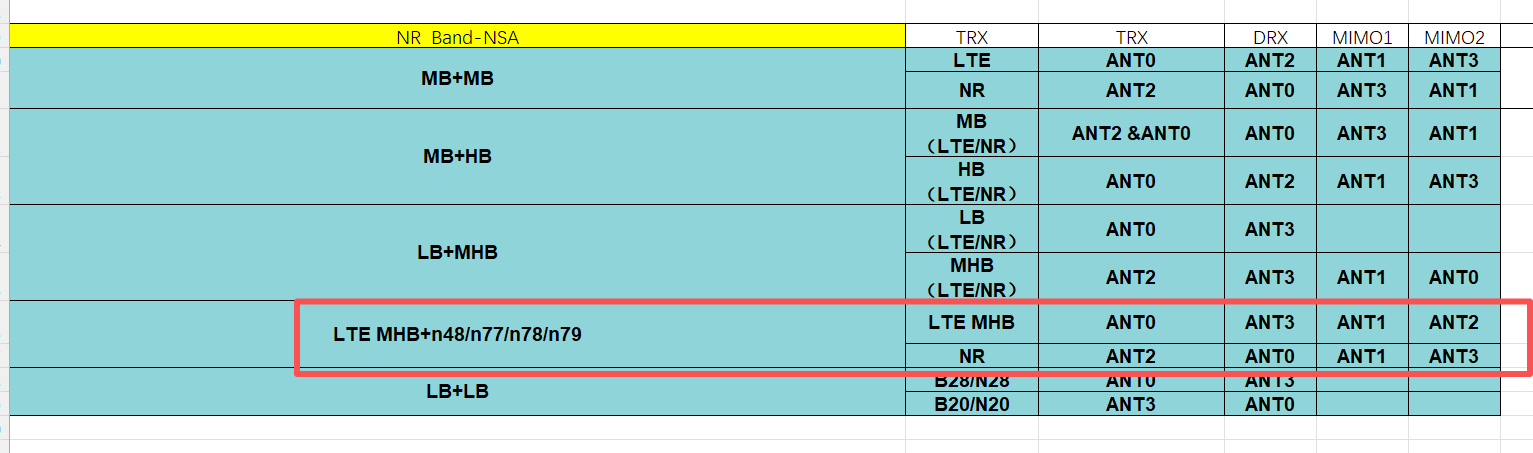
Dear @w6ju9og9w
RM520NGLAAR03A03M4G_A0.305.A0.305 is the latest one.
1.I didn’t find the description in RM520N document. It is not sure whether it supports.
2.Please share your CA combination, I will check the antennas combo.
3.No newer version.
4.For some commands, they don’t support in every 5G module, please refer to document.

Dear @silvia

Under sustained downlink load:

+QCAINFO: “PCC”,1600,100,“LTE BAND 3”,1,421,-97,-15,-62,1
+QCAINFO: “SCC”,325,75,“LTE BAND 1”,1,211,-103,-12,-84,253,0,-,-
+QCAINFO: “SCC”,635040,12,“NR5G BAND 78”,421

+QNWINFO: “TDD NR5G”,“42501”,“NR5G BAND 78”,635040
+QENG: “NR5G-NSA”,425,01,421,-96,15,-10,635040,78,12,1
+QRSRP: -104,-96,-105,-98,NR5G

So the combination is DC_3A-1A_n78A. All four NR receive chains are active and within 9 dB of each other, and NR SINR is 15 dB, so the antenna installation looks healthy from my side.

My core question: is 4×4 downlink MIMO on n78 expected to work on the RM520N-GL in this CA combination? If so, what would prevent the module from using all four receive chains?

Since nr5g_mimo_info is undocumented and nr5g_mimo_layers returns ERROR, is there any supported way to query the actual downlink rank or layer count on n78? Without that I can’t verify whether 4×4 is active.

Context: throughput on this link is 30–50 Mbps typically, peaking at 131 Mbps once. A commercial handset on the same SIM, same cell, same room reaches ~300 Mbps. Signal quality does not appear to be the limit — a sustained 5 dB drop in NR SINR (14 → 9) over several hours produced no measurable change in throughput.

Dear @w6ju9og9w
Please follow the combo of antenna.

Dear @silvia

Following your antenna table, I verified the physical connections. After reseating, AT+QRSRP under load now reads −98 / −99 / −101 / −100 on NR — a 3 dB spread across all four chains, and four active LTE chains as well. This is the best-balanced antenna configuration I have achieved.

Rank is unchanged. Sampling nr5g_mimo_info 60 times under sustained downlink load: rank 2 in 58 samples, rank 3 once, rank 4 once — mean 2.05. My previous baseline across three different antenna orientations was 60 samples each, mean 2.00 in every case.

So with the documented antenna combo in place and all four chains balanced, the module still operates at rank 2 approximately 97% of the time. Throughput is unchanged at ~45 Mbps.

Since rank 4 does occur occasionally, the capability appears present but is rarely selected. What determines the rank the module reports to the network, and what would cause it to report rank 2 under these conditions?

Dear @w6ju9og9w
The Rank Indicator (RI) of 5G is not unilaterally determined by the module, it is a process jointly participated by the network and the terminal.

Dear @silvia

Thank you. I understood that RI is negotiated between the network and the UE via CSI reporting. I have followed the antenna combination table you provided and re-tested. The module still reports 2 layers on n78 under conditions that should support 4.

CURRENT STATE (under sustained downlink load)

  • Firmware: RM520NGLAAR03A03M4G_A0.305.A0.305
  • Combo: LTE MHB (B3 PCC + B1 SCC) + n78, per the highlighted row of your antenna table
  • NR SCC: n78, 100 MHz, RSRP -90, RSRQ -11
  • AT+QRSRP (NR): -94 / -89 / -98 / -93 — four active chains, 9 dB spread
  • AT+QSINR (NR): 16 / 18 / 12 / 15 dB per chain
  • AT+QTEMP: 37-43 C across all sensors (no thermal mitigation)
  • Sustained throughput: ~200 Mbps over a 10 GB transfer

RANK MEASUREMENTS
AT+QNWCFG=“nr5g_mimo_layers” returns 1,2 and AT+QNWCFG=“nr5g_mimo_info” returns ,2,1.

Sampled 60 times per configuration under sustained downlink load, 300 samples total:

  • Cell A, antennas all vertical: mean 2.00
  • Cell A, two antennas at +45 and two at -45: mean 2.00
  • Cell A, all antennas horizontal: mean 2.00
  • Cell B (different PCI, 9 dB better RSRP): mean 2.02
  • Cell B with dis_4mimo_enable set to 0: mean 2.00

Rank 4 appears in roughly 3% of samples, so the capability is present but almost never selected.

CONFIGURATION

  • AT+QNWCFG=“nr5g_4mimo_enable” returns 1
  • AT+QNWCFG=“dis_4mimo_enable” returns 1
  • AT+QNWCFG=“3gpp_rel” returns R16,R16
  • AT+QNWCFG=“lte_ambr” shows no subscription restriction

Setting dis_4mimo_enable to 0, followed by AT+CFUN=0 / AT+CFUN=1, reads back as 0 but produces no change in reported rank or throughput.

COUNTERS THAT DO NOT POPULATE
Under sustained load at ~200 Mbps:

  • AT+QNWCFG=“nr5g_csi” returns 0,0,0,0
  • AT+QNWCFG=“nr5g_dlMCS” returns 0

CONTEXT
A commercial handset on the same network and in the same room, tested alternately rather than simultaneously, reaches approximately 400 Mbps downlink. ~200 x 2 = 400, so the 2-layer limit alone would account for the difference.

QUESTIONS

  1. Can you confirm the field definitions for AT+QNWCFG=“nr5g_mimo_info” and AT+QNWCFG=“nr5g_mimo_layers”? I am reading the layer count from the last field of nr5g_mimo_layers and the third field of nr5g_mimo_info.

  2. What is the difference between dis_4mimo_enable and nr5g_4mimo_enable? Both read 1 on my module, which appears contradictory. What values are required for 4-layer downlink on n78, and why would changing dis_4mimo_enable have no observable effect?

  3. Is there a supported way to read the RI, CQI and PMI the module reports to the network? Under sustained load at ~200 Mbps, nr5g_csi returns 0,0,0,0 and nr5g_dlMCS returns 0, so I have no visibility into either the rank the module requests or the modulation it is assigned. Without that I cannot determine whether the module reports RI=2, or reports a higher RI that the network does not grant — which is the distinction I need in order to know whether the limit is on my side.

  4. Is 4-layer downlink MIMO on n78 expected to work in the LTE MHB + n78 combination shown in your antenna table?

If the module is correctly reporting RI=4 and the network is granting 2 layers, that closes the matter from my side and I will take it up with the operator.

Dear @w6ju9og9w
1.Please share the response of these AT command.
2.dis_4mimo_enable is LTE, nr5g_4mimo_enable is NR5G.
3&4, is it possible to capture log on your side.

Dear @silvia

Thank you for the clarification that dis_4mimo_enable applies to LTE and nr5g_4mimo_enable to NR5G. That resolves the apparent contradiction.

  1. AT COMMAND RESPONSES

All of the following were captured in a single block within one second, under a sustained downlink transfer running at approximately 300 Mbps.

AT+QNWCFG=“nr5g_mimo_layers”
+QNWCFG: “nr5g_mimo_layers”,1,2

AT+QNWCFG=“lte_mimo_layers”
+QNWCFG: “lte_mimo_layers”,1,2

AT+QNWCFG=“nr5g_mimo_info”
+QNWCFG: “nr5g_mimo_info”,635040,2,1

AT+QNWCFG=“lte_mimo_info”
+QNWCFG: “lte_mimo_info”,325,2,1
+QNWCFG: “lte_mimo_info”,1600,2,0

AT+QCAINFO
+QCAINFO: “PCC”,325,75,“LTE BAND 1”,1,-96,-17,-57,0
+QCAINFO: “SCC”,1600,100,“LTE BAND 3”,2,-95,-18,-57,0,0,-,-
+QCAINFO: “SCC”,635040,12,“NR5G BAND 78”,-89,-11,437

AT+QSINR
+QSINR: -5,-5,-2,-1,LTE
+QSINR: 17,19,9,15,NR5G

AT+QRSRP
+QRSRP: -104,-105,-96,-99,LTE
+QRSRP: -93,-88,-99,-94,NR5G

AT+QTEMP (abbreviated)
modem-lte-sub6-pa1: 37, aoss-0-usr: 43, cpuss-0-usr: 43, mdmq6-0-usr: 42,
mdmss-0..3: 41-43, modem-lte-sub6-pa2: 36, modem-ambient-usr: 38

So at 300 Mbps sustained, with four active NR receive chains at -88 to -99 dBm, per-chain NR SINR of 17 / 19 / 9 / 15 dB, and the module well within its temperature range, both nr5g_mimo_layers and nr5g_mimo_info report 2 layers on n78.

  1. RANK SAMPLING

I sampled nr5g_mimo_info repeatedly under sustained downlink load using a script. Five runs of 60 samples each, 300 samples in total:

28 September, cell A:

  • antennas all vertical: rank 1 x1, rank 2 x58, rank 3 x1
  • two antennas at +45 and two at -45: rank 2 x60
  • all antennas horizontal: rank 2 x60

16 October, cell B (different PCI, 9 dB better NR RSRP):

  • default configuration: rank 1 x3, rank 2 x55, rank 3 x1, rank 4 x1
  • with dis_4mimo_enable set to 0: rank 1 x7, rank 2 x49, rank 3 x1, rank 4 x3

Rank 4 occurs occasionally, so the capability appears present, but it is selected in under 3% of samples. Antenna orientation produced no measurable difference across the three geometries.

Regarding dis_4mimo_enable: I set it to 0 and restarted the radio with AT+CFUN=0 / AT+CFUN=1. It reads back as 0, but LTE still reports 2 layers. Current LTE per-chain SINR is -5 / -5 / -2 / -1 dB, so I do not regard this as a valid test of LTE 4x4 - the LTE conditions would not support 4 layers regardless of the setting. I mention it only for completeness.

  1. LOG CAPTURE

Yes, I can capture logs. QWinLog V2.3 is installed and QXDM capture over the USB DM port works.

Before sending a capture, I have a question about the log mask. I examined the default configuration file (conf\qxdm\laptop\laptop_default.cfg) and it enables approximately 1,366 log codes, including the full LTE NAS block (0xB0E0-0xB0EF) and the RRC OTA codes for both LTE and NR5G.

For data protection reasons I would prefer not to transmit a capture containing NAS-layer signalling. Could you provide, or point me to, a configuration file restricted to the NR5G PHY and ML1 codes - approximately 0xB800-0xB814 and 0xB880-0xB8AE - which I believe is where the rank and CSI information resides?

If the UECapabilityInformation and RRCReconfiguration messages are also needed, in order to determine whether the module requests RI=4 and the network grants 2, please say so and I will consider including 0xB821 as well.

Please also confirm two points:

  • Should “Qxdm Sink” be set to USB or PCIE for this module when the PCIe interface is in use for the data path? My carrier board uses PCIe for Ethernet while the USB interface carries AT and DM.
  • Should the capture span registration (AT+CFUN=0 / AT+CFUN=1), or is a mid-session capture under sustained load sufficient?
  1. ONE QUESTION THAT DOES NOT REQUIRE A LOG

Is 4-layer downlink MIMO on n78 expected to work on the RM520N-GL in the LTE MHB + n78 combination shown in your antenna table? A yes or no would tell me whether I am pursuing something the module supports in this configuration.

For reference: firmware RM520NGLAAR03A03M4G_A0.305.A0.305, nr5g_4mimo_enable = 1, 3gpp_rel = R16,R16, no AMBR restriction, antennas connected per your table.

Dear @w6ju9og9w
I don’t heve filter only capture NR5G PHY and ML1 codes .
Please use full filter to capture, I will share to you via Message, please check later.
Don’t worry, I don’t share your information to others.
For log, please include AT+CFUN=0/AT+CFUN=1/ heavy loading.

Dear @silvia

Thank you for offering to send the full filter. Before using it, I captured the RRC signalling myself and analysed it locally, and I believe it already answers the question we were trying to settle with the log.

I used QCSuper against the module’s DIAG port to produce a pcap, triggered a re-registration with AT+CFUN=0 / AT+CFUN=1, and decoded the result in Wireshark. The relevant fields are below.

  1. WHAT THE MODULE ADVERTISES

UECapabilityInformation, featureSetsDownlinkPerCC - six entries, all identical:

maxNumberMIMO-LayersPDSCH: fourLayers (1)

So the module reports four-layer downlink capability to the network.

  1. WHAT THE NETWORK CONFIGURES

RRCConnectionReconfiguration, in the embedded NR secondary cell group configuration:

pdsch-ServingCellConfig → maxMIMO-Layers: 4
codebookConfig → nrOfAntennaPorts: moreThanTwo (1)
codebookConfig → TypeI-SinglePanel-Restriction: all bits set (no codebook subset restriction)
codebookConfig → typeI-SinglePanel-ri-Restriction: 0f [8 bits, 0000 1111]

The cell configures more than two CSI-RS ports with no codebook subset restriction, and the ri-Restriction bitmap permits rank indicators 1 through 4.

So the network permits four layers, configures four layers, and transmits more antenna ports than four layers would require.

  1. WHAT THE MODULE ACTUALLY REPORTS

Sampling AT+QNWCFG=“nr5g_mimo_info” under sustained downlink load, 60 samples per run, 360 samples in total across six configurations:

Cell A, antennas all vertical: rank 1 x1, rank 2 x58, rank 3 x1
Cell A, two antennas +45 and two -45: rank 2 x60
Cell A, all antennas horizontal: rank 2 x60
Cell B, default: rank 1 x3, rank 2 x55, rank 3 x1, rank 4 x1
Cell B, dis_4mimo_enable = 0: rank 1 x7, rank 2 x49, rank 3 x1, rank 4 x3
Cell B, best channel conditions: rank 1 x4, rank 2 x52, rank 3 x1, rank 4 x3

The final run was taken under the best conditions I have been able to achieve:

AT+QSINR → NR5G: 18 / 19 / 15 / 17 dB (4 dB spread across the four chains)
AT+QRSRP → NR5G: -90 / -89 / -99 / -92 dBm
AT+QCAINFO NR SCC SNR: 10.89 dB
AT+QTEMP: 37-43 C across all sensors
nr5g_4mimo_enable: 1
3gpp_rel: R16,R16

Even there, the module reported 2 layers in 87% of samples and 4 layers in 5%.

  1. THE QUESTION

The module advertises four layers. The network grants four layers. The cell has 32 CSI-RS ports and does not restrict the rank indicator below 4. All four receive chains are within 4 dB of each other at 15-19 dB SINR. The module is well within its temperature range.

Under these conditions, why does the module report RI=2?

I have tested and eliminated every external explanation available to me: three antenna geometries, two different cells, chain balance from a 10 dB spread down to 4 dB, thermal throttling, and both MIMO configuration flags. Rank 4 does occur in roughly 3-5% of samples, so the capability is clearly present in the implementation - it is simply almost never selected.

  1. ON THE LOG

I would still prefer not to transmit a capture taken with the full filter, since it includes NAS-layer signalling. I hope the RRC field values above are more useful in any case, since they isolate the question to the module’s CSI reporting rather than leaving it open whether the network is refusing.

If your engineers need something specific from the PHY or ML1 layers that would explain the rank selection, please tell me which log codes carry it, and I will see whether I can capture and review that subset.

Dear @w6ju9og9w
It is better to share log to us for analysis.

Dear @silvia

I understand that a full log is what your engineers would normally work from, and I am not trying to make this difficult.

The difficulty on my side is that a .qmdl is a binary file I cannot audit. I have no way to inspect what it contains before sending it, and the default filter enables the full NAS block, which carries subscriber and device identities, APN, assigned addresses and subscription parameters. I am not able to disclose a file whose contents I cannot verify.

This is not a question of trusting you personally. It is that I cannot confirm what I would be handing over.

What I can do is provide any specific decoded values you ask for. I have the RRC signalling decoded locally and can read any field in it, and I can run any AT command sequence under any conditions you specify.

So my question is whether you can help me from what I have already provided. To summarise it:

  • The module advertises maxNumberMIMO-LayersPDSCH: fourLayers on all six downlink feature sets
  • The network configures pdsch-ServingCellConfig → maxMIMO-Layers: 4
  • The codebook is configured with nrOfAntennaPorts: moreThanTwo and no subset restriction
  • typeI-SinglePanel-ri-Restriction is 0f, permitting rank indicators 1 to 4
  • nr5g_4mimo_enable reads 1, and 3gpp_rel reads R16,R16
  • Across 360 samples in six configurations, two cells and three antenna geometries, nr5g_mimo_info reports 2 layers in 87-100% of samples and 4 layers in 0-5%
  • The best run was taken with per-chain NR SINR of 18/19/15/17 dB, NR RSRP of -90/-89/-99/-92 dBm, and the module at 37-43 C. It still averaged 2.05 layers.

Nothing in the capability exchange or the network configuration restricts the module below four layers, and rank 4 does appear occasionally, so the capability is present in the implementation.

Given that, is there a known reason why the module would select RI=2 under these conditions? Specifically:

  1. Are there internal thresholds or margins in the rank selection on this firmware branch that would hold RI at 2 at this SINR?

  2. One receive chain reads consistently 6 to 10 dB below the others in RSRP (-99 dBm against -89 to -92), even when the SINR spread is only 4 dB. Would that alone be sufficient for the rank estimator to settle on 2 layers?

  3. Is there a newer firmware for the GL variant in which rank selection on n78 behaves differently?

If none of those apply and the log is genuinely the only route, please tell me which specific log codes carry the rank and CSI decision. If I can capture that subset and review it before sending, I am willing to do so.

Thank you for your patience with this.

Dear @w6ju9og9w
As you mentioned, the module reports max MIMO layers :4.
For qmdl file, R&D will use QXDM to analysis and try to find why the speed is lower than bandset.
Deteiled information need to check in log, not guess from description.
Thanks for your understanding.

Dear @silvia

Thank you. I understand that your R&D team works from the log and that analysis from a description is not how they operate.

As I said in my earlier messages, my position has not changed: I cannot send a binary file containing sensitive information that I am unable to audit. The constraint is not trust, it is that I have no way to inspect the contents before sending.

That leaves two possibilities.

The first is that you send me an application that can open or parse the QXDM binary, so that I can review the capture myself before deciding what to share. If I can see what is in the file, I can make an informed decision about sending it, and I can also extract and provide whatever specific values your R&D team needs. I understand QCAT is the usual tool for this; if it or any equivalent parser can be made available to me, I am willing to proceed.

The second is that we have reached a dead end, in which case I would appreciate it if you could post an update here should your R&D team identify the cause by other means. Given that the behavior appears to be reproducible - the module reports 4-layer capability, the network configures and permits 4 layers, and the module still selects RI=2 under good conditions - I would expect it to be observable on your own test equipment without my log.

Either way, thank you for the time you have put into this.

Dear @w6ju9og9w
Reading from nr5g_mimo_info reflects the layers actually scheduled by the gNB (QXDM 0xB887), not the rank the module decides to report. Our own R&D position is that the scheduled MIMO layers are network-controlled; the module cannot force 4 layers if the gNB does not grant them.
As mentioned before,the Rank Indicator (RI) of 5G is not unilaterally determined by the module, it is a process jointly participated by the network and the terminal.

QXDM need license, we can’t share to you.