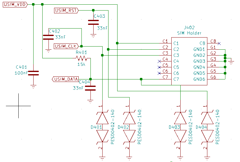
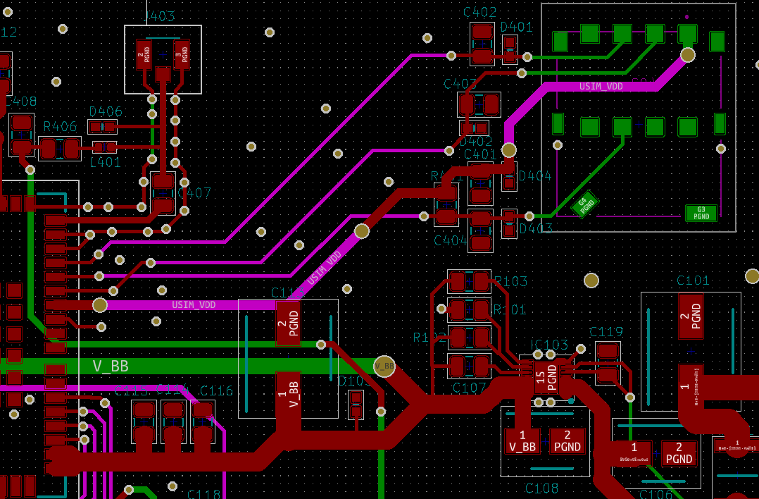
I recently completed the hardware design for my board, which has a BG95 M3 on it, and I am trying to test the communications of the modem. I inserted my SIM card which is from Hologram IOT and used the command AT+CIMI which is supposed to return the IMSI number of the card. Instead I am getting the response: “ERROR”. What does this mean that I have a hardware problem or is there something I need to activate before my BG95 will read the card? For example I am not reading any voltage on the USIM_VDD, except at boot which can’t be right.
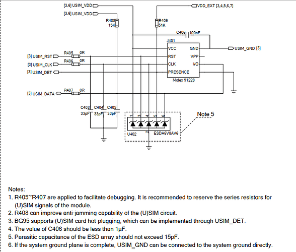
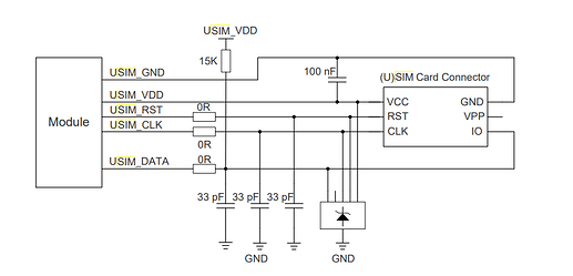
The figure you posted was for the SIM card holder with card detection, I used the diagram below for design, also from the hardware integration manual. It doesn’t feature sim detection.
This is what I am seeing.
15:28:16.188 -> AT+QCCID
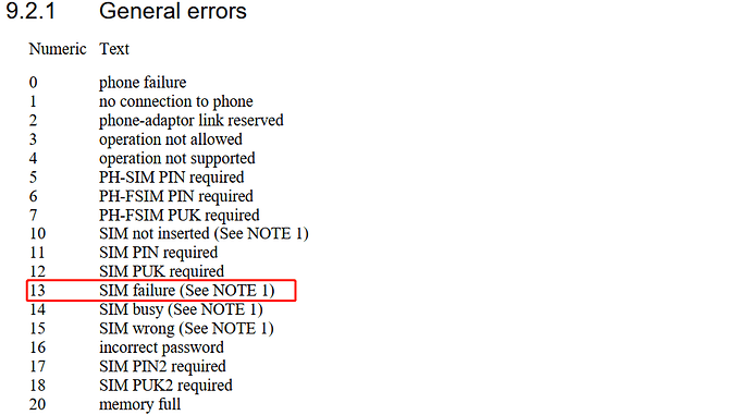
15:28:17.312 -> +CME ERROR: 13Thank you for your reply, but could you elaborate I don’t know what source this is from or what “SIM failure”: entails?
hi,feynman137:
It’s not clear if it was caused by some kind of interference or welding error.
I recommend that you disconnect all connections from the SIM and then directly connect the SIM card slot/holder to the SIM pin of the modem through the cable,And retest the SIM.
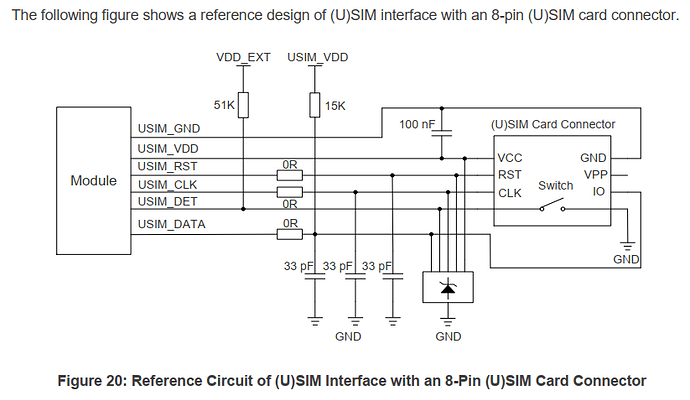
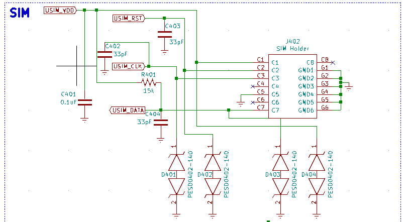
Problem was resolved on a different forum. But in case anyone in the future refers to this post the circuit diagram I posted above is incorrect in 2 aspects. The C5 contact should be connected to GND and the data line capacitors should be in pF not nF, don’t know how this one slipped by.
Here is the correct diagram.
