PCM signal issue

Hello, I designed a PCB which contains a Texas Instruments Codec TLV320AIC3256 and a EG915U LTE Module, the Codec logic voltage level is set to 3.3V, so I used a bidirectional voltage level translator from Texas Instruments as well, TXS0108E. Since the Codec I am using is not one of the automatically supported ones of the LTE module, I am using a custom Codec configuration.

When executing the “AT+QAUDSW=0” command to use an external codec, I get error 0x85, so, that is supposed to mean that no external Codec is recognized, and the internal Codec is still the one who is working no? How the EG915U determines if there’s a Codec connected or not?

I measured BCLK and WCLK signals with an oscilloscope, and I could see that the signals on both sides of the voltage level translator are not as expected (the attached image corresponds to the 1.8V side of the signal), but the other signals connected to the same voltage level translator from the MCU (MSP432) to the EG915U seem just fine (Airplane mode signal, UART signals, etc.), so, it doesn’t seem like a voltage translator issue.
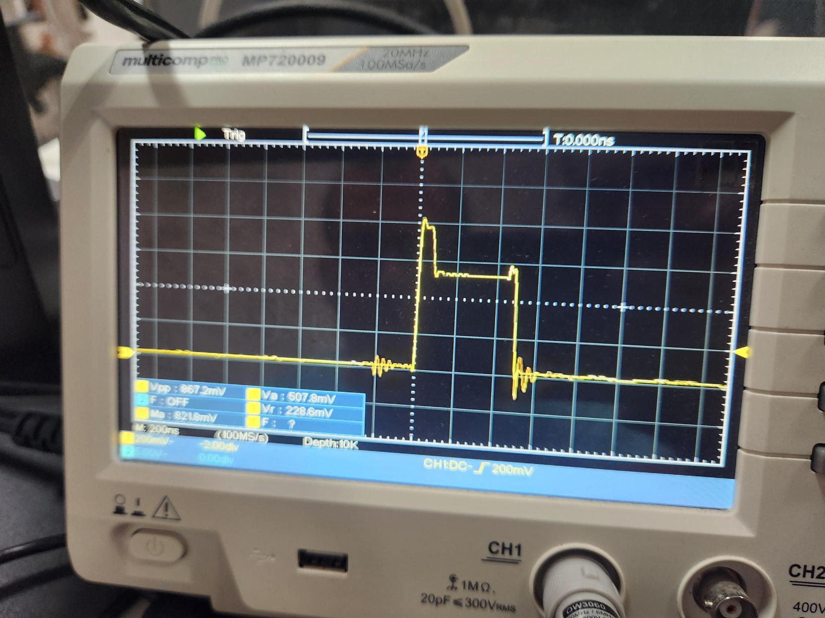
I tried using termination resistors and parallel capacitors, but nothing changed. So, I disconnected the BCLK signal from the Codec to the TXS0108E and connected an external 2MHz signal to the same input (to simulate BCLK signal) and the result was the same, so it doesn’t seem like a BCLK trace issue. Finally, I connected the BCLK signal from the Codec to the Airplane Mode signal on the voltage level translator, and the 1.8V output was as expected. So, that tells me that the problem is in the LTE’s BCLK and WCLK input.

What I would like to know is that maybe some misconfiguration could cause contention in the bus and that could be causing the signal loss, or if there’s something else I am missing.

Thanks in advance, best regards.

Hi @Alex_Luaces_Garcia
Thank you for the detailed information and for sharing the results of your measurements.

Based on the current test results, I suspect that the issue may be related to the digital audio interface configuration, particularly the BCLK/WCLK direction or possible contention between the EG915U and the TLV320AIC3256.

Here are some suggestions for further debugging steps:

  1. Confirm the audio clock master/slave configuration

Please verify which device is configured as the master for BCLK and WCLK.

There should be only one device driving each clock signal:

  • If EG915U is the master: EG915U should drive BCLK/WCLK and the TLV320AIC3256 should receive them.
  • If TLV320AIC3256 is the master: TLV320AIC3256 should drive BCLK/WCLK and EG915U should receive them.

Please make sure both devices are not configured to drive the same BCLK/WCLK lines, as this could cause bus contention and result in a distorted or collapsed waveform.

  1. Check the EG915U audio interface configuration

Please confirm the custom codec configuration, especially the parameters related to:

  • Digital audio interface mode (I2S/PCM)
  • Master/slave mode
  • BCLK direction
  • WCLK/FSYNC direction
  • BCLK frequency
  • WCLK frequency
  • Data format
  • Clock polarity

the module support NAU88C10 and ALC5616 as the digital codec.

  1. Perform a test without the TLV320AIC3256 connected

If possible, disconnect the codec from the BCLK/WCLK lines and apply an external 2 MHz clock directly to the corresponding side of the level translator.

Then compare the waveform at:

  • TXS0108E input
  • TXS0108E output
  • EG915U BCLK pin

If the waveform is already distorted at the EG915U side while the codec is completely disconnected, this would help isolate the issue from the TLV320AIC3256.

  1. Check for contention

With the oscilloscope, please measure BCLK/WCLK under the following conditions:

a. EG915U connected, codec disconnected
b. EG915U disconnected, codec connected
c. Both EG915U and codec connected

If the waveform is normal in (a) and (b) but becomes abnormal in (c), this would strongly indicate contention or an incorrect master/slave configuration.

  1. Check the signal directly at the EG915U pin

Please compare the waveform before and after the level translator, and also measure as close as possible to the EG915U BCLK/WCLK pins.

If the waveform is clean at the TXS0108E output but becomes distorted only when connected to the EG915U, this would indicate that the EG915U pin configuration/loading may be affecting the signal.

If the waveform is already distorted at the TXS0108E output, then we should focus on the level translator and its configuration.

Once the basic clock waveform is confirmed, the remaining codec configuration can then be enabled step-by-step.

At this stage, our main suspicion is the BCLK/WCLK direction or master/slave configuration, with the TXS0108E being another item that should be eliminated as a possible cause.

Could you please provide the following information for further analysis?

  • EG915U firmware version
  • Complete TLV320AIC3256 custom codec configuration
  • EG915U digital audio configuration/AT command sequence
  • Oscilloscope captures of BCLK and WCLK on both sides of the TXS0108E
  • Whether the TLV320AIC3256 or EG915U is configured as the BCLK/WCLK master

With these details, we can further check whether the issue is caused by codec configuration, clock direction/contention, or the level translator.

Thank you and have a nice day!

Hi @Firdaus, thank you for your response.

Here you can find my answers and tests results about each point you mentioned:

  1. According to ``EG915U Series Hardware Design´´ version 1.4, the EG915U only supports slave mode, but, when I execute AT+QDAI=?, the module returns: +QDAI: (1,3),(0),(0,1),(4),(0),(0),(1),(1) which should mean:

    = 1,3 (NAU88C10, ALC5616),
    = 0 (Master mode),
    = 0,1 (PCM short sync, IIS short sync),

    = 4 (2048 kHz),
    = 0 (16-bit lineal),
    = 0 (8 kHz),
    <num_slots> = 1,
    <slot_mapping> = 1

    Which is odd, because here says nothing about user-defined external codec, which, according to the hardware design document, is supported, and there it is also said that only supports master mode (when the device returns that only master mode is supported). The hardware design document also says that clock, format, sample, num_slots and slot_mapping parameters are not supported as well. It is also mentioned in the hardware design doc that the EG915U only supports PCM mode, but the command returns that it supports IIS protocol as well.

    To summarize, I see many differences between the hardware design document and the parameters returned by the EG915 module.

    Then I executed AT+QDAI=1,1,0,4,0,0,1,1 which stands for:

    = 1 (NAU88C10),
    = 1 (Slave mode), (which shouldn’t work according to the module’s response that only supports master mode),
    = 0 (PCM short sync),

    = 4 (2048 kHz),
    = 0 (16-bit lineal),
    = 0 (8 kHz),
    <num_slots> = 1,
    <slot_mapping> = 1

    I realized here that the module is not recognizing the User-defined external Codec command, which according to the hardware design doc, should work just fine, but the module itself says that it’s not supported. What could be the cause of it? The exact part number of the module on the board is EG915UEUAB-N05-SNNSA, which is, EG915U indeed.

  2. Point 2. answer is mixed with the 1.

  3. With the BCLK’s Codec signal disconnected, I applied a 2MHz signal generated by the board’s MCU, the signal is distorted at both sides of the TXS0108E. This was the same MCU’s pin that handled the EG915U Airplane mode, which waveform was originally OK when it was connected to EG915U’s W_Disable pin, which means that the track layout associated to that pin has no issues.

  4. Suggested tests results:
    a. EG915U connected, codec disconnected: the signal is 0V flat .I don’t know if this is the result of a default pull-down in the EG915U’s BCLK pin, or that the module is actively driving this pin low, but measuring it with the voltmeter results in a 22 Ohms resistance to GND.
    b. EG915U disconnected, codec connected: The signal seems just fine at both ends of the TXS0108E.
    c. Both EG915U and codec connected: The signal is distorted at both ends of the TXS0108E, this is the original case in the board.

    Photos of these cases are attached in the PDF file.

  5. EG915U firmware version: EG915UEUABR02A05M08.
    Complete TLV320AIC3256 custom codec configuration: Codec is configurated as master, since the EG915U is only supposed to support slave mode. Frequencies: WCLK: 8 kHz and BCLK: 2048 kHz. 16 bits, PCM, default non-inverted polarity.
    EG915U digital audio configuration/AT command sequence: explained in point 1.
    Oscilloscope captures of BCLK and WCLK on both sides of the TXS0108E: find them attached in PDF file.

My main suspicion is that the configuration the EG915U says it supports, differs from the one written in the hardware design file.

Best regards.

BCLK Singal Waveform.pdf (378.4 KB)

Hi @Alex_Luaces_Garcia
Thank you for your response.
I will send you a follow up email to your email address. Kindly check on your side.

Hi @Firdaus,

I sent you a response email yesterday, I hope you received it, so we can keep discussing about the signal issue.

Best regards.

Hi @Alex_Luaces_Garcia
Let’s continue in the email loop.