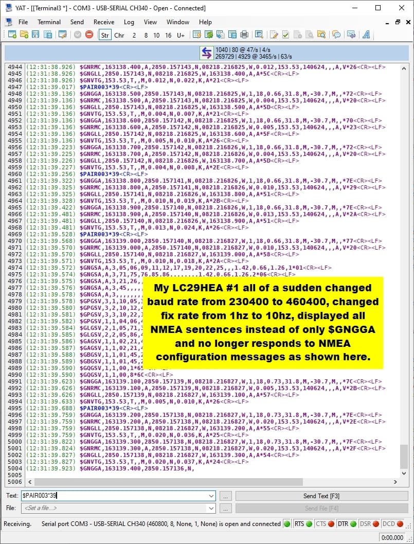
After running stable for a few days, the first one of my LC29HEA’s (#1) seems to have reverted to factory defaults and no longer recognizes any NMEA configuration messages as you can see here:
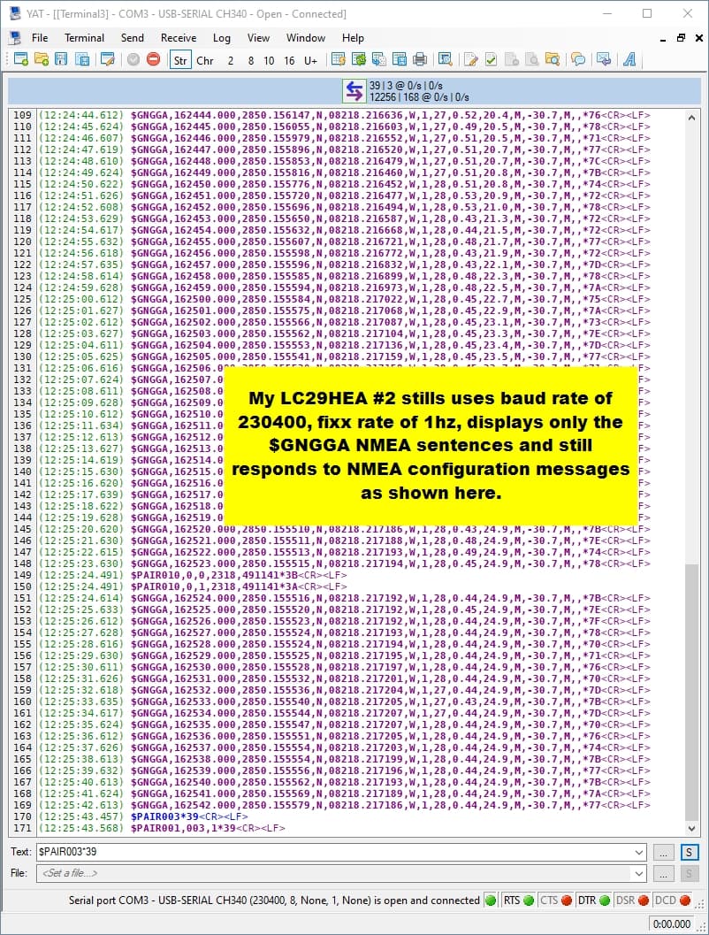
My first and second LC29HEA’s were configured IDENTICALLY a few days ago and #2 still works as expected, here is a serial stream capture I made just before the above capture:
I have tried many serial terminal programs to send NMEA configuration messages to my (apparently RESET) #1 EVB (QGNSS v1.1, Satrack, CoolTerm and YAT) without success. This is the first time that YAT can not configure an LC29HEA for me 
Any ideas how to recover my LC29HEA #1?
Thanks,
Dale
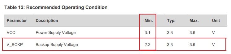
EDIT: I thought I would check the voltage of the batteries which are soldered to the boards and I am even more confused now  :
:
Battery on #1: is 1.99V without USB plugged in and 2.70V with USB plugger in.
Battery on #2: is 0.68V without USB plugged in and 2.05V with USB plugger in.
Hi Marco,
Unfortunately, neither shorting the Header GND pin to the reset pin on the LC29H module nor shorting the Header GND pin to the Header RST pin causes a Reset and the Firmware Download does not proceed past the ‘Handshake’ stage…
Dale
EDIT: I am grasping at straws now, perhaps I should try un-soldering the battery and then re-soldering it, in hopes that it returns to a good state for re-flashing…
Hi DaleCKramer
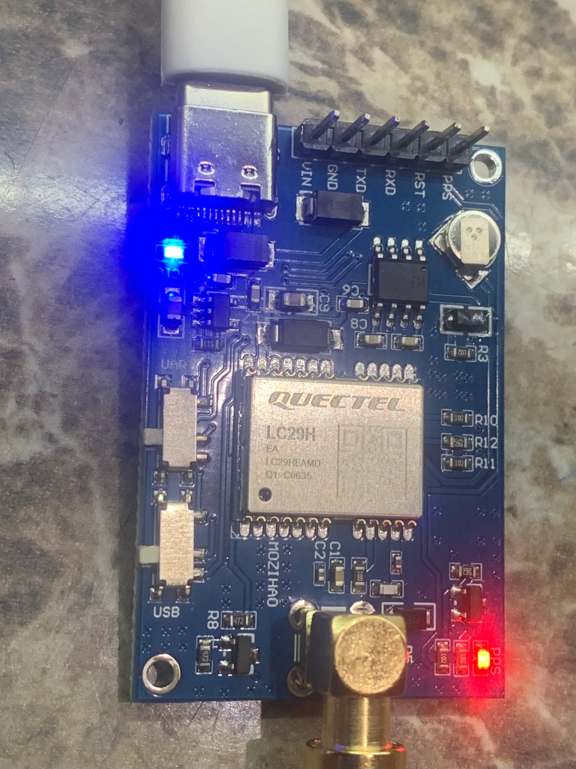
As you can see on the hardware board you provided, you can choose USB or UART communication. Please make sure to select the UART interface when upgrading.
From the log, we can see that you sent instructions to the first module. What instructions did you send and what operations did you perform? Please provide them.
Hi George,
I do all communication with both boards using the UART that is connected to the USB port and the board switches as shown in the pic of the board.
With the suspect board, I had previously re-loaded the latest firmware (LC29HEANR11A03S_RSA,2023/10/31,16:52:14) using QGNSS V1.10 and the reset for firmware load was successfully accomplished by shorting to GND, the reset pin on the LC29HEA pcb reset pad. I was reliably able to get responses to many commands until the LC29HEA just magically reset and stopped accepting commands. Now I have tried many commands and have had no responses.
In the first image you can see I tried to stop the GNSS with $PAIR003*39 many times and had no responses at all (In the first image, BLUE text is USB serial data sent to the LC29HEA and MAGENTA text is USB serial data being received).
EDIT:
More info: The suspect LC29HEA EVB also does not respond to any commands when using the UART that is connected to the EVB boards header pins either and just to be clear, the LC29HEA is sending out all expected NMEA data at 10hz from BOTH UART connections.
My battery voltage confusion in my first post was that #2 was only 2.05 volts. That is not a confusion between module #1 and #2.
Module #2 is sending and receiving data on the TX and RX lines with only 2.05v on its battery while plugged into USB.
Module #1 is the suspect module but has 2.7v on its battery when USB is plugged in..
Why are you having me work on module #2 ??
In any case, I removed the battery on suspect #1 and supplied 2.984v to the module battery pads with no luck, LC29HEA is still not receiving data from USB nor UART pin RX connections.
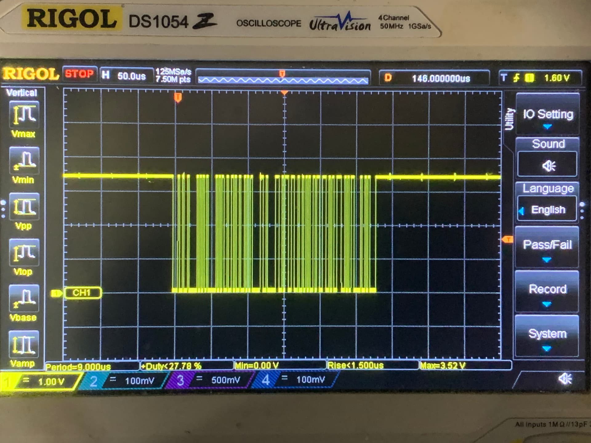
Here is the suspect module #1 RX bit pattern I captured on my scope for the $PAIR003*39 command when using the header pinned UART:
EDIT: Using my scopes ASCII decoder, these pulses do represent the 11 characters of $PAIR003*39.
Also, shouldn’t these modules work even without a battery installed ?? I would think that the only advantage of have a battery voltage within the working range would be to allow much faster time to 1st fix after a power up of the module…
Hi DaleCKramer
The purpose of replacing the battery is to verify whether the module abnormality is caused by voltage problems.
Since module 2 is still normal after replacement, change the conditions of module 1 to the same as module 2 (including voltage), and test the performance of module 1 and the level of RX when receiving instructions. Please also provide the logs of module 1 and module 2. The logs need to be captured from power-on.