MC60 I2C fails to read

Hi.

I am trying to read the ID of an IMU chip with I2C Address 0x18. The connections are:
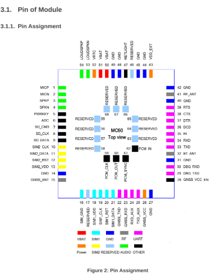
RI <----> SCL
DCD <----> SDA

There is a 2.8V power supply for the IMU chip and 2.8Kohms pull up resistors for the I2C lines.

The Open CPU code is the following:

void proc_main_task(s32 taskId)
{
s32 ret;
ST_MSG msg;

// Register & open UART port
Ql_UART_Register(UART_PORT1, CallBack_UART_Hdlr, NULL);
Ql_UART_Open(UART_PORT1, 115200, FC_NONE);

Ql_UART_Register(UART_PORT2, CallBack_UART_Hdlr, NULL);
Ql_UART_Open(UART_PORT2, 115200, FC_NONE);


APP_DEBUG("\r\n<--OpenCPU: IIC TEST v4!-->\r\n");
APP_DEBUG("\r\n<--IMU Test \r\n",ret);
iRet = RIL_GPS_Open(1);
if(RIL_AT_SUCCESS != iRet)
{
    APP_DEBUG("Power on GPS fail, iRet = %d.\r\n", iRet);
}
else
	APP_DEBUG("Power on GPS Successful.\r\n");

init_iic();


while (1)
{
    Ql_OS_GetMessage(&msg);
    switch(msg.message)
    {
    case 0:
        break;
    default:
        break;
    }
}

}

void init_iic()
{
ret = Ql_IIC_Uninit(1);
ret = Ql_IIC_Init(1,PINNAME_RI,PINNAME_DCD,1); //Start I2C Communication
if(ret < 0)
{
APP_DEBUG("\r\n<–Failed !! IIC controller Ql_IIC_Init channel 1 fail ret=%d–>\r\n",ret);
}
APP_DEBUG("\r\n<–IIC controller Ql_IIC_Init ret=%d–>\r\n",ret);

ret = Ql_IIC_Config(1,TRUE, addr, 300); // just for the IIC controller

if(ret < 0)
	{
		APP_DEBUG("\r\n<--Failed !! IIC controller Ql_IIC_Config channel 1 fail ret=%d-->\r\n",ret);
	}
	APP_DEBUG("\r\n<--IIC controller Ql_IIC_Config ret=%d-->\r\n",ret);


//ret = Ql_IIC_Write(1, addr, write_buffer,2); //Clear PWR_MGMT_1 register 6B to 00
ret = Ql_IIC_Read(1, addr, 0x00, 1,read_buffer, 1); //Read WHO_AM_I register for MPU-6050
if(ret < 0)
{
	APP_DEBUG("\r\n<--Failed !! IIC controller Ql_IIC_Read channel 1 fail ret=%d-->\r\n",ret);
}
APP_DEBUG("\r\n<--IIC controller Ql_IIC_Read ret=%d-->\r\n",ret);


//SerialPrint("–Who am I----->%X",read_buffer);
 APP_DEBUG("\r\n<--IMU ID %x %d-->\r\n",ret,ret);
u8 c=read_buffer;
if(c==0x16)
{
	 APP_DEBUG("\r\n<--Accelereometer OK-->\r\n");
}

}

After Flashing the MC60, I got the following output:

2020-01-27 02:49:06:890_R:] <–OpenCPU: IIC TEST v4!–>

[2020-01-27 02:49:06:890_R:] <–IMU Test
[2020-01-27 02:49:06:890_R:] Power on GPS fail, iRet = -5.

[2020-01-27 02:49:06:890_R:] <–IIC controller Ql_IIC_Init ret=0–>

[2020-01-27 02:49:06:890_R:] <–IIC controller Ql_IIC_Config ret=0–>

[2020-01-27 02:49:06:890_R:] <–Failed !! IIC controller Ql_IIC_Read channel 1 fail ret=-1–>

[2020-01-27 02:49:06:890_R:] <–IIC controller Ql_IIC_Read ret=-1–>

[2020-01-27 02:49:06:890_R:] <–IMU ID ffffffff -1–>

Any advise why the I2C Read command returns a negative value? What does it mean?

The I2C Init and Configuration return correct values though.

#define SLAVE_ADDRESS ( 0x18 << 1 ) /* Mediatek I2C slave address 8 bits */

Hello

I already shift the address one bit so I have it defined as:

//IMU Vars
u8 addr = 0x30;
s32 ret, iRet;

Checking the scope, I see both SCL and SDA going low at the same time for 8 us and then going high. I was expecting clock pulses on the SCL.

Question:

I added pull up resistors 2.7Kohms to 2.8V power supply for both SCL, SDA, is this necessary? I am assuming the Quectel chip does not have strong pull ups?

I rectified one line of code:

ret = Ql_IIC_Read(1, 0x00, read_buffer, 1); //Read IMU Chip ID

and the ret value is -34 which looks like:
QL_RET_ERR_I2CHWFAILED = -34,

The INIT and CONFIG calls returns 0, not sure what am I missing?

thanks in advance

QL_RET_ERR_I2CHWFAILED “mean” … SDA pul-up is too low … try 4.3k … 10k

Hi

I tried 10K. And now the response is the following:

[2020-01-29 05:48:09:485_R:] <–IIC controller (chnnlNo 1) Ql_IIC_Uninit ret=0–>
[2020-01-29 05:48:14:908_S:] Ql_IIC_Init=1

[2020-01-29 05:48:14:983_R:] <–pins(SCL=2,SDA=3) IIC controller Ql_IIC_Init channel 1 ret=0–>
[2020-01-29 05:48:21:606_S:] Ql_IIC_Read=1

[2020-01-29 05:48:21:681_R:] <–Failed !! IIC controller Ql_IIC_Read channel 1 fail ret=-308–>

I don’t see any activity on the scope for SDA or SCL when issuing the Read command. Init and Config returns 0.

Actually, my bad.

Still the same response after adding 10K pull ups. I was missing the Config Command.

[2020-01-29 05:51:30:643_S:] Ql_IIC_Uninit=1

[2020-01-29 05:51:30:702_R:] <–IIC controller (chnnlNo 1) Ql_IIC_Uninit ret=0–>
[2020-01-29 05:51:33:995_S:] Ql_IIC_Init=1

[2020-01-29 05:51:34:053_R:] <–pins(SCL=2,SDA=3) IIC controller Ql_IIC_Init channel 1 ret=0–>
[2020-01-29 05:51:37:490_S:] Ql_IIC_Config=1

[2020-01-29 05:51:37:549_R:] <–IIC controller Ql_IIC_Config channel 1 ret=0–>
[2020-01-29 05:51:41:251_S:] Ql_IIC_Read=1

[2020-01-29 05:51:41:326_R:] <–Failed !! IIC controller Ql_IIC_Read channel 1 fail ret=-34–>

no idea…
what mean
ret=0 –> … Ql_IIC_Config=1
ret=0 –> … Ql_IIC_Read=1

I am using the following function to Initialize/Configure and Read I2C data:

static void init_iic()
{
ret = Ql_IIC_Uninit(1);
ret = Ql_IIC_Init(1,PINNAME_RI,PINNAME_DCD,1); //Start I2C Communication
if(ret < 0)
{
APP_DEBUG("\r\n<–Failed !! IIC controller Ql_IIC_Init channel 1 fail ret=%d–>\r\n",ret);
}
APP_DEBUG("\r\n<–IIC controller Ql_IIC_Init ret=%d–>\r\n",ret);

ret = Ql_IIC_Config(1,TRUE, addr, 300); // just for the IIC controller

if(ret < 0)
	{
		APP_DEBUG("\r\n<--Failed !! IIC controller Ql_IIC_Config channel 1 fail ret=%d-->\r\n",ret);
	}
	APP_DEBUG("\r\n<--IIC controller Ql_IIC_Config ret=%d-->\r\n",ret);

	time_delay(5000);

//ret = Ql_IIC_Write(1, addr, write_buffer,2); //Clear PWR_MGMT_1 register 6B to 00
ret = Ql_IIC_Write_Read(1, addr, 0x00, 1,read_buffer, 1); //Read WHO_AM_I register for MPU-6050
if(ret < 0)
{
	APP_DEBUG("\r\n<--Failed !! IIC controller Ql_IIC_Write_Read channel 1 fail ret=%d-->\r\n",ret);
}
APP_DEBUG("\r\n<--IIC controller Ql_IIC_Write_Read ret=%d-->\r\n",ret);


//SerialPrint("–Who am I----->%X",read_buffer);
 APP_DEBUG("\r\n<--IMU ID %x %d-->\r\n",ret,ret);
u8 c=read_buffer;
if(c==0x16)
{
	 APP_DEBUG("\r\n<--Accelereometer OK-->\r\n");
}

}

ret=0 is the results of:

  • Init (I2C init with hardware and RI and DCD)
  • Config (Setting Up I2C Slave Address, Host and Speed (300 Khz))

Then I tried to write/read

QL_RET_ERR_I2CHWFAILED = -34
QL_RET_ERR_I2CHWFAILED, Maybe the hardware have something wrong.
thats mean approximately: I2C can not read ACK, problems with level-convertor oр pull-ups

Do you think it is the VCC level?. Currently the Pull ups resistors are connected to 2.8V. should it be 3.3V or even the 4.1V which is powering the MC60?

Can you advise which VCC do you use?

MC60 pins is 2.8v, your sensor is 3.3v, so you need level convertor
Try connect sensor to 2.8 … if can work of 2.8

My IMU is powered using 2.8V power supply which also powers a Flash chip and I can successfully talk to it.

I tried 10K pull ups and 2.7K. Any other suggestions?

are you see clock and data with scope / analizator

Unfortunately I dont see any Clock/Data pulses on the I2C pins. At power up, both SDA and SCL goes low for 4us and they stay high after.

if (1 == IIC_type) // hard IIC controller PINNAME_RI, PINNAME_DCD
if (0 == IIC_type) // soft IIC, PINNAME_GPIO4, PINNAME_GPIO5 for IIC SCL and SDA pins

this say MC60 documentation

CHecking the header file, it shows:

/*****************************************************************

  • Function: Ql_IIC_Init
  • Description:
  •           This function initialize the configurations for an IIC channel.
    
  •           including the specified pins for IIC, IIC type, and IIC channel No.
    
  • Parameters:
  •           chnnlNo:
    
  •               [In] IIC channel No, the range is 0~254
    
  •           pinSCL:
    
  •               [In] IIC SCL pin.
    
  •           pinSDA:
    
  •               [In] IIC SDA pin.
    
  •           IICtype:
    
  •               [In] IIC type,FALSE means simulate IIC, TRUE means hardware IIC.
    

For type =0, it shows “Simulate IIC” which also affects the Configuration function which says that Simulated IIC doesnt require speed set.

/*****************************************************************

  • Function: Ql_IIC_Config
  • Description:
  •           This function configuration the IIC interface for one slave.
    
  • Parameters:
  •           chnnlNo:
    
  •               [In] IIC channel No, the No is specified by Ql_IIC_Init function
    
  •           isHost:
    
  •               [In] must be ture, just support host mode.
    
  •           slaveAddr:
    
  •               [In] slave address.
    
  •           IicSpeed:
    
  •               [In] just used for hardware IIC,and the parameter can be ignored when using simulation IIC.
    
  •                    For hardware IIC, It supports fast mode and high speed mode. the speed of fast speed mode
    
  •                    is less than 400 kbps, and the speed of high speed mode is [400..3400] kbps. 
    

I am using pins 35 and 36 for I2C. The pins that you highlighted on red square are UART TX/RX

ups my error … yes two pins up ( shot )

Hardware connections are good. What I am suspecting is happening the MC60 is not starting any I2C transaction for some reason.

I was expecting a Start I2C behavior but not able to trigger on the scope yet.