@tomm has an esp32 Bluetooth/BLE bridge sw that he posted but I couldn’t get it to compile. I have a much simpler version that works just for Bluetooth, not BLE. The code is posted below:
//This example code is in the Public Domain (or CC0 licensed, at your option.)
//By Evandro Copercini - 2018
//
//This example creates a bridge between Serial and Classical Bluetooth (SPP)
//and also demonstrate that SerialBT have the same functionalities of a normal Serial
#include “BluetoothSerial.h”
#if !defined(CONFIG_BT_ENABLED) || !defined(CONFIG_BLUEDROID_ENABLED) #error Bluetooth is not enabled! Please run make menuconfig to and enable it #endif
#define TX1 2 #define RX1 4 // Don’t use 0, some devices can’t drive it
// #define DEBUG // For testing on monitor
int buffer;
BluetoothSerial SerialBT;
void setup() {
Serial.begin(230400);
SerialBT.begin(“RTK-GNSS”); //Bluetooth device name
Serial1.begin(460800, SERIAL_8N1, RX1, TX1);
Serial.println(“”);
Serial.println(“The device started, now you can pair it with bluetooth!”);
}
void loop() {
while (Serial1.available()) { // For high speed, clear out the input buffer
buffer = Serial1.read();
SerialBT.write(buffer); #ifdef DEBUG
Serial.write(buffer); // Also write out to serial monitor #endif
}
while (SerialBT.available()) { // Less likely to come from App, but use same
buffer = SerialBT.read();
Serial1.write(buffer); #ifdef DEBUG
Serial.write(buffer); #endif
}
}
#if !defined(CONFIG_BT_ENABLED) || !defined(CONFIG_BLUEDROID_ENABLED) #error Bluetooth is not enabled! Please run make menuconfig to and enable it #endif
BluetoothSerial SerialBT;
HardwareSerial uart(2) ; // UART2 #define RX 16 //ESP32 #define TX 17 //ESP32 #define packTimeout 5 #define PACKET_SIZE 4096
byte buf1[PACKET_SIZE];
int i1=0;
byte buf2[PACKET_SIZE];
int i2=0;
int RTCM_length=0;
int bt_len=0;
int bufsize=0;
void setup() {
Serial.begin(460800);
uart.begin(460800, SERIAL_8N1, RX, TX);
SerialBT.begin(“ESP32”); //Bluetooth device name
Serial.println(“The device started, now you can pair it with bluetooth!”);
xTaskCreatePinnedToCore(loop2,“loop2”,8192,NULL,1,NULL,ARDUINO_RUNNING_CORE);
}
I’ll try it. Your code uses the hw uart as well as both processors which should help with processing power but the single core and sw uart appears to be able to handle 460800bps fine without any problems.
I want to get @tomrm’s code going because it supports BLE, which should work with ios. Right now, my forwarder only works to an Android device.
Ok spleen, thanks for your information.
I’m jealous because I still haven’t been able to get data and I see that you have solved it. congratulations.
Questions: 1) how do you power the two modules: esp32 and lg290?.
You power the esp32 directly and then connect the lg290p to the 3.3v and gnd pins of the esp32 or you have two separate power lines.
2) which uart did you use? the one silk-screened on the back of the rtxd1 and txd1 module or the other one (rtxd2 and txd2)?
My esp32 is powered by USB input to it, which is 5V. Even though the esp32 is 3.3v device, most esp32 modules will bring the 5V out to a Vcc pin, so I connect that Vcc to the Vin of the LG290P board. I presume you have the Mozihao board. The board has an onboard regulator so you can connect 5v to power it. So the power goes like this: USB 5V into esp32, VCC from esp32 board to Vin of LG290P board.
SInce UART1 of the Mozihao board is shared between the USB and TXD1/RXD1, it is best to use UART2 (TXD2/RXD2) to connect to your serial forwarder if you still want USB access to the module for configuration.
Thanks spleen, so you take the 5v current from the vcc pin of the esp32 to connect it to the VIN pin of the UART2 socket?? I have always connected the vcc 3.3v pin of the esp3 to the VIN pin of the gps module: so have I always been wrong!? I don’t want to burn the lg290p module!
I have already “burned” (perhaps) an LC2929EA module because I soldered some wires directly onto the RX R TX pins of the CIP with the result that the module now does not output any data, not even from the UART-USB socket which previously worked correctly.
I will try your suggestions on my lg290p.
and @falajons ,
Fate attenzione al voltaggio, anche io ne ho fritti due di moduli per averli connessi a un adattatore usb-ttl
Leggete bene il voltaggio supportato…se avete un tester misurate l’uscita che è meglio.A proposito della mozihao board, potrebbe esere stato un difetto della saldatura, ma non conviene mai tentare di saldare se non si dispone di adeguata attrezzatura…e comunque la uart2 del modulo lc29h non è abilitato su -ea di default, io avevo una -aa che si è fritta dopo pochi secondi, per il voltaggio a 3 ma 5 su tx ed rx…
P.S
negli schetch notate le virgolette “ & ” vanno corrette con " & "
Buona continuazione e complimenti per la vostra tenacia.
However, the Quectel specs on the LG290P module doesn’t claim 5v tolerance, so take it with a pinch of salt. I know the esp32 i/o pins are 5V tolerant and I do use them that way, but this is a relatively expensive chip, so keep it at 3.3v
I should add that the Mozihao board MAY have clamping diodes on the uart input that allows it to accept 5v input safely. I don’t have the schematic so can’t really tell…
Ok thanks to both of you for your interest and assistance.
LG290P power supply: I think @milza is right because when I power the GPS module with the 3.3v of esp32 the power LED has low brightness and variable intensity.
But given the risks, then I power it (the GPS) separately from the esp32 module.
LC29HEA module problem: I tried to solder two wires to the cip pinouts of the LC29EA module because by touching them directly with the tip (bypassing UART) I saw output data.
The module is not 100% dead or “fried” (I hope): the two integrated LEDs flash correctly and GNSS connects but does not receive position data from UART-USB.
Question: Can the above module be reset via hardware?
I understand your cautiousness, but there is really no risk in powering the GPS from the esp32 Vcc pin, if you are powering the esp32 from USB. That voltage won’t be higher than your USB power, which is 5V. The esp32 board typically has an onboard regulator that produces the 3.3v from the Vcc.
I don’t have a LC29 board, but from pictures I’ve seen, it’s very similar to the LG290P board. In fact, the document I have for the LG290P board still has LC29 left in all over it. Those boards have a CH34x USB-serial chip which is connected to uart1, selected via the two switches. It’s possible you fried the CH34x chip but the uart output from the LG29 is still good. I’m guessing you don’t have an oscillioscope to look at voltage signals? One last thing to try is to try the switch settings? Maybe you just inadvertently switched the USB off?
infatti anche @tomrn ha fritto …
comunque all’epoca del 29h-ea chiesi a mozihao la doc. 396.31 MB folder on MEGA
non ricordo se manca la cartella 3 ma il link al cloud era cinese e lo feci riversare su uno accessibile comunque il link era questo: 百度网盘-链接不存在 Extraction code: 5rvh
ormai scaduto.
That’s excellent! Now I finally have a schematic, and know what both of the switches do! Anyway, the Mozihao module definitely has a 3.3v regulator so it’s safe to input a range of voltages to Vin.
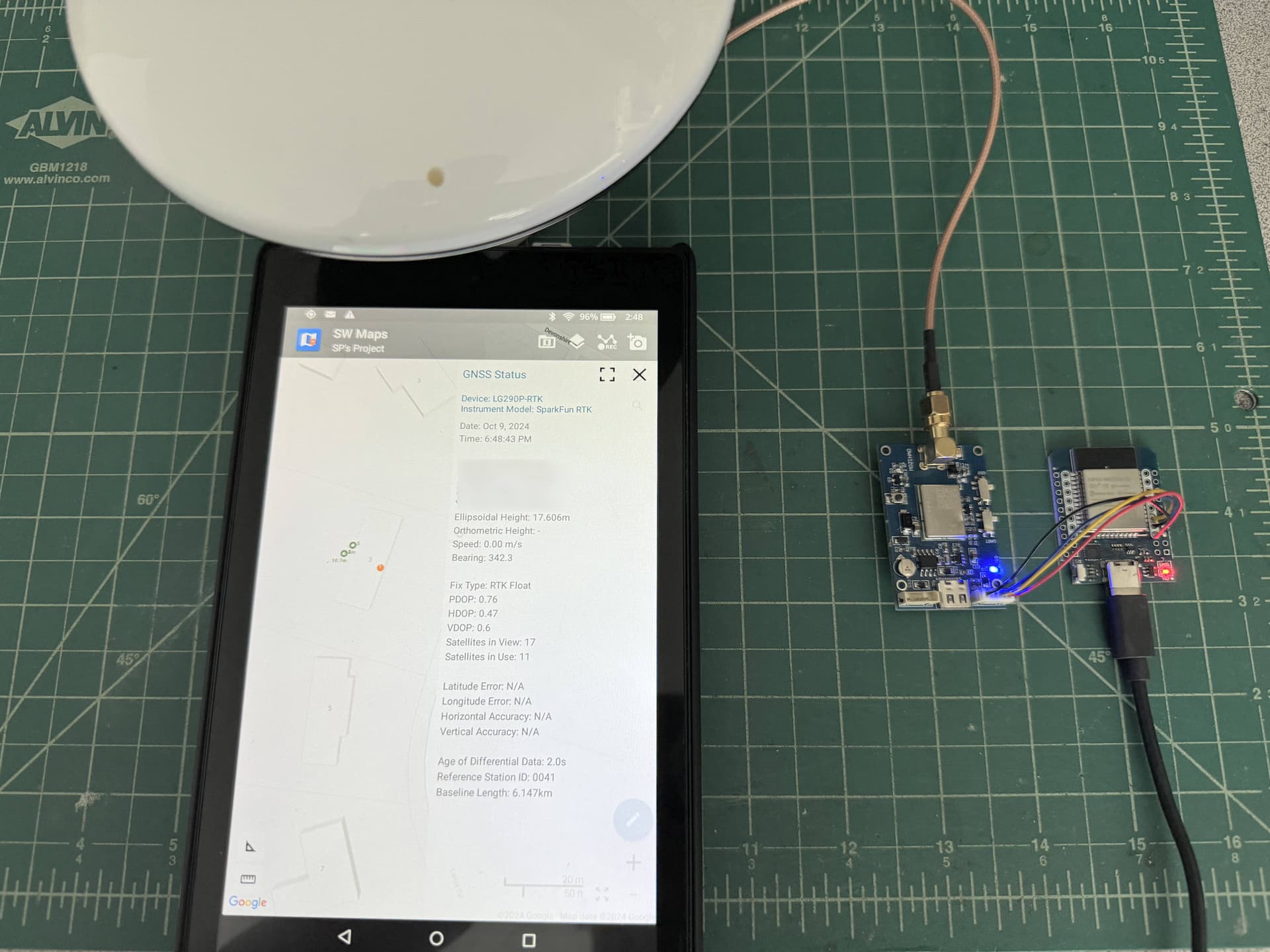
@falajon, just so you have a better idea, here is how my boards are connected for my Surveyor set-up:
Just 4 wires connect the boards together, and the USB cable to the esp32 is connected to a USB power bank, which provides power to both the boards. SW Maps is connected via Bluetooth to the esp32 and is receiving location as well as sending NTRIP correction information to the GPS. It’s indoors, so can only achieve RTK Float status.
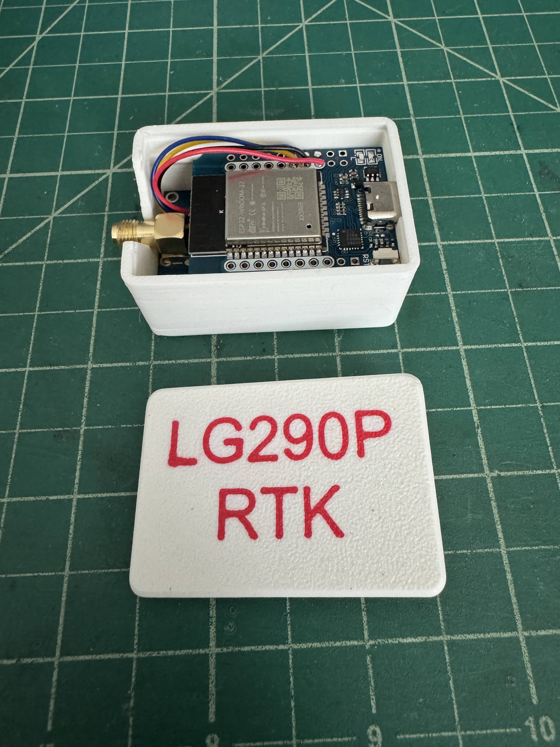
Both boards are packaged into a box which I clip to my surveyor pole, along with the antenna and a USB power bank. It works very well for
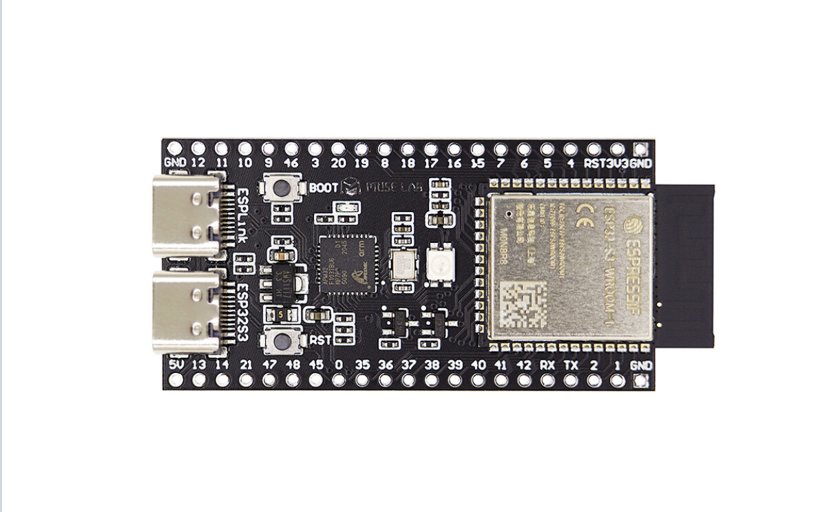
has anyone tried to use an ESP32 S3 with 2 USB type C ports? One USB port is able to act as OTG port an can power the LG290P board direct by an USB connection.
Does anyone have code or knows a link to GitHub for creating an USB (OTG) BLE bridge?
I want to avoid using UART port of LG290P board and it is much more easier to use an USB OTG cable to connect the ESP32 S3 to the LG290P or any other module.
Thanks @splee for sharing the information.
Question: I see in the photo that the UART switch of the GPS module is up and not down! Shouldn’t it be down?
Greetings and have a good day
AF
@falajons I found the schematic for the mozihao board and the switch positions are as follows:
Both switches UP, towards antenna and USB silkscreen = USB port is active for UART1 Both switches DOWN, away from antenna = TX1/RX1 pins are active for UART1
UART2 is always active on TX2/RX2 pins, which is what I use to talk to the esp32