LC29H Not Responding to UART Commands

I am currently using the LC29H in a design and the module is not responding to any $PAIR commands via UART.

My setup consists of a ESP32-MINI-1 as the MCU utilizing UART_NUM_1 with a bidirectional level-shifter between the TX and RX pins of the LC29H module to convert logic level +3V3 to +2V8. I have connected a logic analyer to both the ESP32-MINI-1 and the LC29H module and the $PAIR commands look fine over the wire on both the LC29H and ESP32 end.

No matter which command I try, there is no response from the LC29H module nor is there any change in the desired settings. Also, in the LC29H GNSS protocol specification document there are no suggestion to the default settings for UART other than default baud 115200.

Please see below for my UART config on the ESP32-MINI-1:

const uart_config_t uart_config = {
.baud_rate = 115200,
.data_bits = UART_DATA_8_BITS,
.parity = UART_PARITY_DISABLE,
.stop_bits = UART_STOP_BITS_1,
.flow_ctrl = UART_HW_FLOWCTRL_DISABLE,
.source_clk = UART_SCLK_DEFAULT,
};

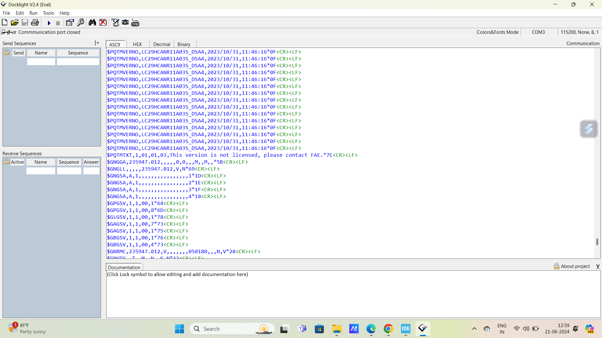
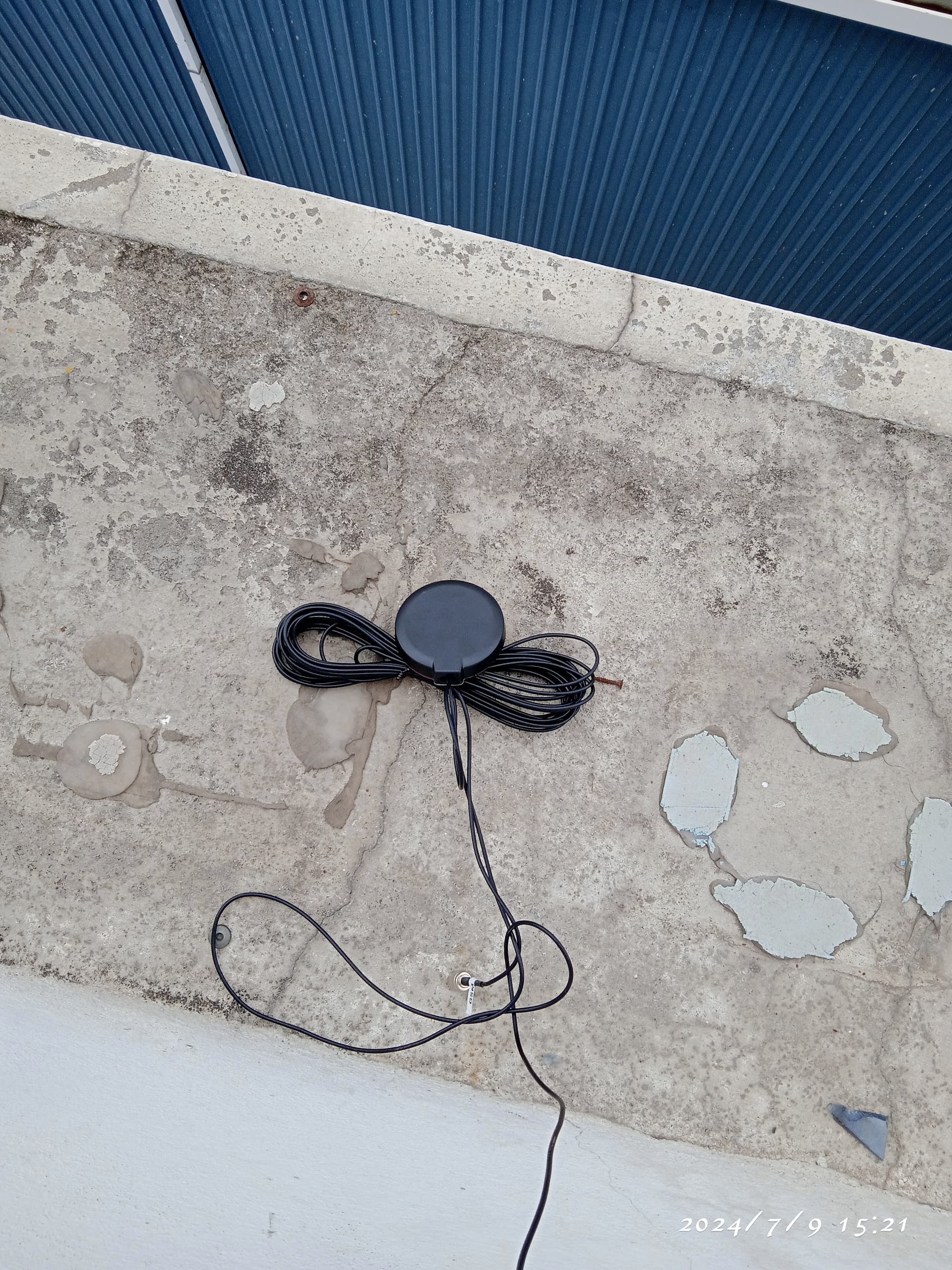
Here is a sample response (note my antenna is disconnected but this has no impact):

W (9532) UART_TX_TASK: Wrote lc29 command $PAIR062,2,03c
of length 17 and response tx_bytes 17
I (10402) uart_events: read data:
$GNGGA,002203.000,0,00,99.99,M,M,4B
I (10402) uart_events: read data:
$GNRMC,002203.000,V,060180,N,V
25
I (10412) uart_events: read data:
$GNGLL,002203.000,V,N
67
I (10412) uart_events: read data:
$GNVTG,T,M,N,K,N32
I (10422) uart_events: read data:
$GNGSA,A,1,99.99,99.99,99.99,1
33
I (10432) uart_events: read data:
$GNGSA,A,1,99.99,99.99,99.99,230
I (10432) uart_events: read data:
$GNGSA,A,1,99.99,99.99,99.99,3
31
I (10442) uart_events: read data:
$GNGSA,A,1,99.99,99.99,99.99,436
I (10452) uart_events: read data:
$GNGSA,A,1,99.99,99.99,99.99,5
37
I (10462) uart_events: read data:
$GPGSV,1,1,00,164
I (10472) uart_events: read data:
$GPGSV,1,1,00,8
6D
I (10472) uart_events: read data:
$GLGSV,1,1,00,178
I (10482) uart_events: read data:
$GAGSV,1,1,00,7
73
I (10482) uart_events: read data:
$GAGSV,1,1,00,175
I (10492) uart_events: read data:
$GBGSV,1,1,00,1
76
I (10492) uart_events: read data:
$GBGSV,1,1,00,572
I (10502) uart_events: read data:
$GQGSV,1,1,00,1
65
I (10512) uart_events: read data:
$GQGSV,1,1,00,86C
E (10522) uart_events: [UART DATA]:
$PQTMDRCAL,1,0,0
5D

Could use some help to figure out what is wrong as I feel like I have exhausted all options. Has anyone else dealt with this?

Here is the device readout on boot:
LC29HCANR01A05S_DSA2CRLF

Hi Cykibb,

Did you try to use USB to TTL sending commands to LC29H module? If the MCU can not send commands to module, maybe because LC29H’s RXD is occupied.

How is the situation on your logic analyzer? What’s the maximum voltage of RXD pin?

Best regards.

I am facing same issue and voltage at RXD pin 0.75v and TXD is 2.8V, can you tell me what is the solution for this issue .

Hi vijayamounika_laxven
Is your mode used alone or connected to an external MCU?
The module’s RX defaults to 2.8V. The RXD pin you measured is 0.75v, which may be because your circuit pulls RX down. It is recommended that you check the hardware circuit. TXD is 2.8V. One possibility is that the module is sending a message. The second possibility is that the module is abnormally pulled up. Please check the circuit.

Is there any sequence of commands to getting started LC29H CA

Hi vijayamounika_laxven
LC29HCA does not have a sequence of startup commands, and the module can run immediately after power-on.

Yeah, it’s running but I want to disable some NMEA sentences and I’m sending $PAIR062 message and successful ack also received but still the messages are coming For example i want to disable GGA ,even after disabling it is coming again and again how to exactly disable them And another problem is even after connecting antenna for continuously 2 days it doesn’t acquire location at.

Hi vijayamounika_laxven
I have confirmed that the $PAIR062 command can turn NMEA messages on/off.
Please send the command “$PQTMVERNO*58” to query the current software version number of the module and inform me.


it is showing $PQTMVERNO,LC29HCANR11A03S_DSA4,2023/10/31,11:46:16*0F

Hi vijayamounika_laxven
Your module software is not activated. Please contact your local FAE for activation.

Does LC29H CA has any command to know ANTENNA status?
How to check whether antenna is connected or not?

Hi vijayamounika_laxven
LC29HCA does not support antenna detection.
To determine whether the antenna is connected successfully, you can see whether the module can search for satellites in an open environment and whether the CN value of the search is around 40.

what is CN value? how to find it?

Hi vijayamounika_laxven
You can use the QGNSS tool, where the “Signal Level” interface will display the satellite number, frequency band and CN value. QGNSS download address: QGNSS_V1.10_CN | 移远通信 (quectel.com.cn)
CN value is shown in the figure below

Hi George,
even after software activation I’m not able to get GPS fix. I have connected passive antenna and the circuit is also as per hardware design guide provided by quectel . And the time in NMEA msg is just incrementing when module is started.

Hi vijayamounika_laxven
After activating the module, you must reset the module so that it can work normally.
Can you send me the log file you captured?
And take a picture of your module connection and test environment, thank you.

I’ve reset the module using RESET pin. but response is still same as per attached log


LC29H_CA_LOG.txt (61.1 KB)

Hi vijayamounika_laxven
According to the test log, no constellation was found in about 100s of testing.

  1. What type of antenna are you using? Is it an active antenna or a passive antenna? Do you have an antenna specification sheet?
  2. Measure the module’s PIN9 and PIN14 to confirm whether they are both high level? The PIN pins are shown in the figure.
    image

We are using passive antenna and for antenna specification please refer to attached document.
PIN 9 AND PIN14, both pins are high level (3.25V).