Is it possible to purchase one GNSS module in a specific version, which will also support RTCM in 10Hz and have an IMU sensor? I mean the LC29H series
I would like to know if a GNSS module with an IMU sensor will offer inertial data for use by an external system or application. Is the inertial data generated by the sensor used to generate NMEA frames - inside the module - with already corrected positioning data, based on the IMU sensor?
What should be the signal on PIN2 (FWD) I know it’s digital, but what parameters? voltage/frequency?
PIN17(Warning Indicator) what is it for? What is it warning me about?
1.LC29H (BA) and LC29H (CA) support 6-axis IMU
2.OK. GNSS modules with IMU (inertial measurement unit) sensors typically provide inertial data for consumption by external systems or applications. Inertial data generated by these sensors can be used inside the module to generate NMEA and be corrected with GNSS positioning data. By using MU data, the accuracy and reliability of positioning can be improved.
3.Typical voltage domain is 1.8V
4.WI is a wake-up indication pin, mainly used for trailer detection
Is NMEA auto-correction using IMU data always on? Do I need any commands to run it and configure it?
I wonder if the height of the IMU system can be entered into the system? Because if there is a displacement in the Y axis, i.e. ROLL and NMEA correction, then the height from the ground on which the vehicle is driving will be required and unevenness of this ground causes the antenna to tilt (displace), but the actual position of the vehicle does not change.
Before IMU start to work, the module need a calibration. DR does not need to be recalibrated after each power-up, and the module outputs position information immediately after power-up in the case of no signal(since LC29HBANR01A03S_CSA4).
Altitude data is calculated by not only DR but also GNSS 3D fix. Mostly, GNSS positioning takes the lead to calculate altitude. RTK will help promote vertical precision.
the module gives us two types of sentences that carry information about the location:
PQTMINS and PQTMGPS
Which one is corrected using data from the IMU?
Both PQTMINS and PQTMGPS are supported by 2-wheel vehicles(firmware ending like _CSA2 or _DSA2). And both of them are from IMU. It depends on which parameter you need.
It depends on your application. Generally, we sell LC29H(DR supported model) with 4-wheels version.
You can query firmware version by sending $PQTMVERNO*58
It does not work. The system indicates that it is after calibration, I use $PQTMINS for location and after placing the module 2.3 m above the ground, on the bike, I tilt the bike while driving and the points drawn on the map move left and right and are not corrected by the ROLL parameter.
Maybe I should calculate the position correction in an external application based on data from the LC29 module.
As I wrote at the beginning, the system cannot calculate the tilt to the sides because it does not know its height from the ground. Therefore, based on the data from GNSS + IMU, we add to this the height of the antenna from the ground and calculate ourselves that the deviation occurred by 30cm and we go back by that
I checked carefully by drawing the coordinates on the map. $PQTMINS and $PQTMGPS do not compensate for antenna tilt.
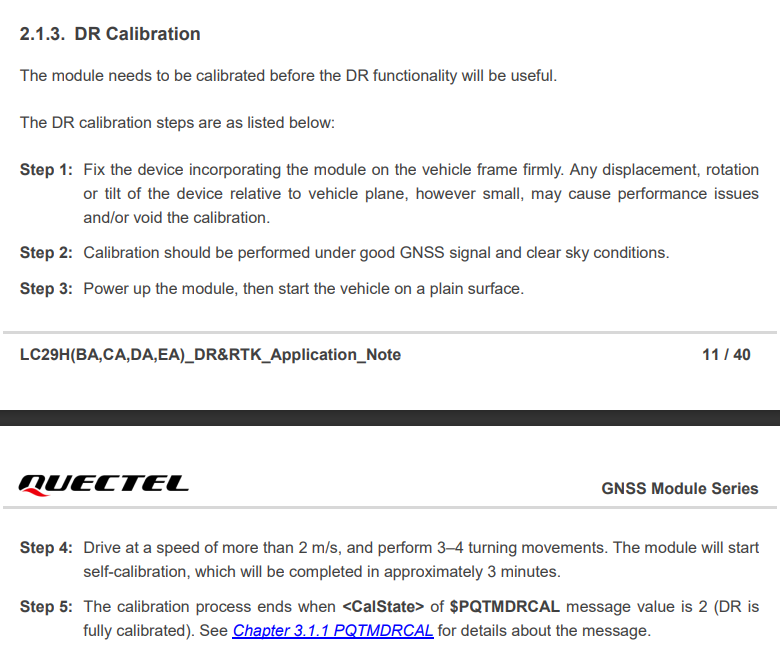
My question from the previous post is still valid, but reading further into the documentation, I got to the DR calibration level parameter. The $PQTMDRCAL frame indicates lightly calibrated or full. The question is what are the conditions for full calibration and will it positively affect the compensation of the antenna tilt?