Hello,
I am using the Quectel L86-M33 GNSS module in a rocket payload PCB. The module will be powered from a regulated 3.3 V rail. I am trying to design the VCC power supply filtering/decoupling properly.
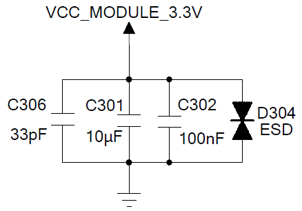
My current plan for the L86-M33 VCC pin is:
-
10 µF capacitor to GND
-
100 nF capacitor to GND
-
Both capacitors placed close to the VCC/GND pins
I also have the option to add an additional 1 µF capacitor in parallel if needed.
My questions are:
-
Is 10 µF + 100 nF sufficient for the L86-M33 VCC supply decoupling?
-
Would adding an additional 1 µF capacitor improve stability against peak current transients, or is it unnecessary?
-
Do you recommend using a ferrite bead or 0-ohm resistor between the main 3.3 V rail and the GNSS module VCC, followed by local capacitors?
-
Are there any specific layout recommendations for the L86-M33 power supply pins, especially for applications with nearby switching regulators and RF modules?
The system also includes an STM32 microcontroller, MS5611 pressure sensor, and an E22 LoRa module, so I want to keep the GNSS power supply as clean and stable as possible.
Thank you.