Hello everybody,
I hope this email finds you well.
I am reaching out to you in my capacity as a university student finishing my project of 5G RedCap to request your guidance regarding a detail we have identified in the 5G-M2 EVB User Guide (Version 1.1.0), specifically within the “Power Consumption Test” section.
While preparing our test procedures, we noticed a potential inconsistency in the instructions for connecting the external power supply to perform this test:
- On one hand, the step-by-step procedure for the “Power Consumption Test” indicates that the external power supply should be connected directly to the VCC and GND points (which, based on Figure 6 and Table 2, correspond to the current test holes H0101 and H0102).
- On the other hand, the specifications section and the block diagram/flowchart in the document appear to indicate that the power supply should be provided through the external power connector J0105.
This discrepancy creates some uncertainty about the correct connection method. To ensure the proper execution of our tests and to avoid any potential damage to the hardware or inaccurate current measurements, we would like to confirm which is the correct approach. Should the power be injected directly through the VCC/GND points (H0101/H0102), or should the J0105 connector be used for this specific test?
We would greatly appreciate your clarification on this matter before we proceed with the validation testing.
Thank you for your time and support. I look forward to your confirmation.
Best regards,
Andrei Piposi
Quectel_5G-M2_EVB_User_Guide_V1.1.0_Preliminary_20230717.pdf (2.9 MB)
Dear Quectel Support Team,
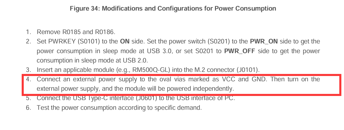
We are using the Quectel RG255C-GL M.2 module on the 5G-M2 EVB (v1.3) for a 5G NR SA RedCap research project. We have followed Section 5.7 of the 5G-M2 EVB User Guide v1.1.0 step by step to perform the power consumption test, but we are facing an issue with the USB interface during the test.
What we did (step by step):
- Removed resistors R0185 and R0186 as indicated in the procedure.
- Connected a Joulescope JS220 in series between an external DC power supply (3.7 V / 2 A) and the VCC/GND test vias (H0101/H0102) on the EVB, to measure the module current consumption.
- Set S0201 to ON and S0101 ON.
- Connected J0601 (USB 3.0 Type-C) to the PC to send AT commands and monitor the module.
In our normal setup (before removing R0185/R0186), the EVB is powered through J0202 using a 5V/3A mains DC adapter (wall plug). Everything works correctly in this configuration: PWRLED ON, WWANLED ON, USB enumerated, AT commands fully functional.
Observed behavior during the power consumption test:
- PWRLED (D0107): ON → the module is receiving power.
- WWANLED (D0108): OFF → RF function is not activated.
- USB (J0601) connected to PC: not enumerated → no COM ports appear in Device Manager, AT commands not possible.
When we re-solder R0185 and R0186 and power the EVB again through J0202 (mains adapter), everything works perfectly again immediately.
Our question:
We believe the issue may be that when R0185/R0186 are removed and the module is powered only through the VCC/GND vias (via Joulescope), the rest of the EVB (USB hub, logic, etc.) has no power supply, which would explain why USB does not work and WWANLED stays OFF.
Could you please confirm if the correct procedure is to simultaneously power the EVB through J0202 (mains 5V/3A adapter) AND feed the module VCC through the vias (via Joulescope) so that:
- The EVB logic and USB interface remain powered and functional.
- The Joulescope measures only the module current consumption through the VCC/GND path.
If this is not the correct approach, could you please clarify how the EVB should be powered during the power consumption test so that the USB interface remains functional for AT command communication?
Thank you very much for your support.
Best regards,
Andrei P
Dear @Andrei_Piposi
Do you have external power supply in your devices?
Hello,
Yes, we followed all the steps you mentioned, and the module starts independently. However, we need to send AT commands through the USB interface in order to perform ping tests and send UDP packets to evaluate its behavior, but it is still not working, as explained in my previous message.
Could you please advise us on how to solve this issue? Alternatively, do you have the electrical schematic of the EVB that you could share with us?
Thank you in advance.
Best regards,
Andrei