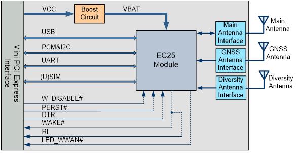
We are going to integrate EC25 Mini PCIe module to a Raspberry Pi module, for data connection.
These are our questions:
- For getting the data connection (ppp) up and running, through USB interface, do we need to still use the UART interfaces (COEX UART and the other full UART)?
- We assume, that when we power up the module and connect the USB on to the host (Raspberry Pi), it should create a couple of interfaces, where one can be used to configure the module with sending AT commands and one of them is to bind with the ppp connection for data?
- Is there a reference schematics build around the EC25 PCIe board (that is, a schematics that shows how the EC25 Mini PCIe is interfaced to another host)?
- Can we leave the following signals unconnected and just the USB interface connected and get the module up and running with data?
a. COEX_UART_RX
b. COEX_UART_TX
c. UART_RX
d. UART_TX
e. UART_RTS
f. UART_CTS
g. DTR
Also, is there any document that gives us the complete instructions, how to install the linux drivers and start the data service (ppp) on a Linux machine (Raspberry Pi), when the EC25 Mini PCIe is connected to the host machine through USB?
Dinesh.
