EC21 QuecOpen GPIO

Hi,

I’m using:
Quectel
EC21
Revision: EC21EFAR06A05M4G

SDK is: EC21EFAR06A05M4G_OCPU_20.001.20.001_SDK

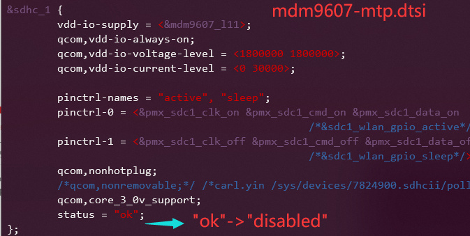
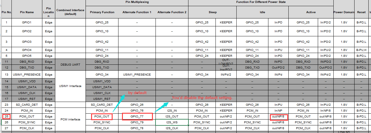
I need to remap some GPIO pins for example PCM_IN (pin 24) and PCM_OUT (pin25) and many others as inputs and outputs.

I did a test but using function

Ql_GPIO_Init(PINNAME_PCM_IN, PINDIRECTION_OUT, PINLEVEL_HIGH, PINPULLSEL_DISABLE);
Ql_GPIO_SetLevel(PINNAME_PCM_IN, PINLEVEL_HIGH);

or

Ql_GPIO_Init(PINNAME_PCM_IN, PINDIRECTION_OUT, PINLEVEL_LOW, PINPULLSEL_DISABLE);
Ql_GPIO_SetLevel(PINNAME_PCM_IN, PINLEVEL_LOW);

to drive the output pin high/low it seems not working.

Is necessary to remap the pin in order to use it as GPIO? Or all the pins listed in “ql_gpio.h” can be used freely?

typedef enum{
    /*Invalid*/ PINNAME_BEGIN = -1,
	/*PIN-1*/  PINNAME_GPIO1 = 1,
	/*PIN-2*/  PINNAME_GPIO2 = 2,
	/*PIN-3*/  PINNAME_GPIO3 = 3,
	/*PIN-4*/  PINNAME_GPIO4 = 4,
	/*PIN-5*/  PINNAME_GPIO5 = 5,
  /*PIN-6*/    PINNAME_PMU_GPIO1 = 6,
	/*PIN-13*/ PINNAME_USIM_PRESENCE = 13,
	/*PIN-23*/ PINNAME_SD_INT_DET = 23,
	/*PIN-24*/ PINNAME_PCM_IN = 24,
	/*PIN-25*/ PINNAME_PCM_OUT = 25,
	/*PIN-26*/ PINNAME_PCM_SYNC = 26,
	/*PIN-27*/ PINNAME_PCM_CLK = 27,
	/*PIN-37*/ PINNAME_SPI_CS_N = 37,
	/*PIN-38*/ PINNAME_SPI_MOSI = 38,
	/*PIN-39*/ PINNAME_SPI_MISO = 39,
	/*PIN-40*/ PINNAME_SPI_CLK = 40,
	/*PIN-41*/ PINNAME_I2C1_SCL = 41,
	/*PIN-42*/ PINNAME_I2C1_SDA = 42,
  /*PIN-61*/   PINNAME_PMU_GPIO4 = 61,
	/*PIN-62*/ PINNAME_GPIO6 = 62,
	/*PIN-63*/ PINNAME_UART1_TX = 63,
	/*PIN-64*/ PINNAME_MAIN_CTS = 64,
	/*PIN-65*/ PINNAME_MAIN_RTS = 65,
	/*PIN-66*/ PINNAME_UART1_RX = 66,
	/*PIN-67*/ PINNAME_MAIN_TX = 67,
	/*PIN-68*/ PINNAME_MAIN_RX = 68,
	/*PIN-73*/ PINNAME_GPIO7 = 73,
  /*PIN-118*/  PINNAME_PMU_GPIO6 = 118, 
	/*PIN-119*/ PINNAME_EPHY_RST_N = 119,
	/*PIN-120*/ PINNAME_EPHY_INT_N = 120,
	/*PIN-121*/ PINNAME_SGMII_DATA = 121,
	/*PIN-122*/ PINNAME_SGMII_CLK = 122,
  /*PIN-127*/  PINNAME_PMU_GPIO3 = 127, 
	/*PIN-129*/ PINNAME_SDC1_DATA3 = 129,
	/*PIN-130*/ PINNAME_SDC1_DATA2 = 130,
	/*PIN-131*/ PINNAME_SDC1_DATA1 = 131,
	/*PIN-132*/ PINNAME_SDC1_DATA0 = 132,
	/*PIN-133*/ PINNAME_SDC1_CLK = 133,
	/*PIN-134*/ PINNAME_SDC1_CMD = 134,
	/*PIN-135*/ PINNAME_WAKE_WLAN = 135,
	/*PIN-136*/ PINNAME_WLAN_EN = 136,
	/*PIN-137*/ PINNAME_COEX_UART_RX = 137,
	/*PIN-138*/ PINNAME_COEX_UART_TX = 138,
  /*PIN-139*/  PINNAME_PMU_GPIO2 = 139,  
	/*PIN-141*/PINNAME_I2C2_SCL = 141,
	/*PIN-142*/PINNAME_I2C2_SDA = 142,
	/*PIN-143*/PINNAME_GPIO8 = 143,
	/*PIN-144*/PINNAME_GPIO9 = 144,
    PINNAME_END
}Enum_PinName;

By the way: if I use PINNAME_GPIO_3 it works.

Thank you

Yes.

Some GPIOs might be used for another purposes. eg, PINNAME_PCM_IN is used in PCM. You’d disable it in the kernel device tree.

Dear @Bean.Wang-Q,

Can you please tell me how to disable PCM (and SDC1 pin 129 to pin 136) in order to use those pins as GPIO?

Or, where can I find the kernel device tree?

Thanks you for support and Regards

eg.
To use the SDC1 related IO as gpio

image

1 Like

Hello @Bean.Wang-Q,

Thank you very much for explaining the location of the file and the necessary edit.
Once I “disable” the SDC1 should I re-compile the entire SDK, isn’t it?

make
make all

Regarding PCM_OUT pin, should I change gpio77 to gpio25 or do I need to comment out the definition of the pin (the highlighted part in grey of your last post)?

sec_auxpcm_dout_active: sec_auxpcm_dout_active {
	mux {
		pins = "gpio25";
		function = "sec_mi2s";
	};
	config {
		pins = "gpio25";
		drive-strength = <8>;   /* 8 MA */
		bias-disable;           /* No PULL */
		output-high;
	};
};

Thank you and regards

No. You can use the gpio sysfs (/sys/class/gpio) to control the GPIO. And the PIN25 actually is the gpio77. gpio77 is the gpio sequence of Linux kernel, and the 25 only can be used in QuecOpen API.
I’m not quite sure how to disable the PCM in dtsi.
To use the Pin25, you could try to remove all the node of sec_auxpcm_dout_active related in the device tree. Maybe it is still not working.

Yes.

Thanks @Bean.Wang-Q,

I’m still failing to understand how to use PCM pins as standard GPIO. If I list /sys/class/gpio I got

/sys/class/gpio # ls
export        gpio14        gpio21        gpio25        gpiochip1018  gpiochip916
gpio10        gpio15        gpio22        gpio42        gpiochip820   gpiochip948
gpio1018      gpio16        gpio23        gpiochip0     gpiochip852   gpiochip980
gpio13        gpio17        gpio24        gpiochip1012  gpiochip884   unexport

I don’t see any gpio77 and I don’t how to enable it in kernel device tree.
I tried changing value of “gpio25” but it controls PIN1 of the module (as correctly reported in the documentation).
So my question is: how to include “gpio77” in /sys/class/gpio folder?
Is there a “simple method” maybe using “make kernel_menuconfig” menu?

Regarding SDC1 pins: I have changed “ok”->“disabled” in dtsi file and then recompiled the SDK and updated the module using the new files:

mdm9607-perf-boot.img
mdm9607-perf-sysfs.ubi
usrdata.ubi
usrdata.ubifs

However I have the problem how to test on UTMS&LTE_EVB_v2.2 board. I don’t know where the SDC1 pins are located in order to test. Are you able to tell me where they are in the PCB?

Thanks and regards

For the PIn25

/sys/class/gpio# echo 77 > export
cd gpio77
/sys/class/gpio/gpio77# echo out > direction
/sys/class/gpio/gpio77# cat direction
/sys/class/gpio/gpio77# echo 1 > value
/sys/class/gpio/gpio77# cat value
/sys/class/gpio# echo 77 > unexport

For the GPIO test, it’s better to use the LTE OPEN-EVB_SCH Board.

Hello @Bean.Wang-Q,

Thanks for the code. I’m able to export different gpio (for example gpio17, gpio15, gpio77) and if I read the “value” as input it works.

However, if I attempt to follow your instruction and drive the pin as output, it doesn’t work.

If I do for gpio25 (pin 1 of EC21->GPIO1) it works!

So I do not undestand how to drive, for example pin134 -> SDC1_CMD -> GPIO17, as an output. How to do that?

Moreover, once I export those GPIO in /sys/class/gpio, how do I use those pins in QuecOpen?

Thank you and regards

Hello @Bean.Wang-Q,

In order to proceed our project design, we changed some pins as GPIO assignment respect the original ones.

Most of them are working. It remains only 3 pins (pin129, pin130, pin131 which are SDC1_DATA3, SDC1_DATA2, SDC1_DATA1) which should be used as INPUTS.
Can you please show me how to setup those pins to be able to be initialized and read in QuecOpen?

Thanks!

You’d better to ask the sales for the Quectel_EC25&EC21-Quecopen_GPIO_Assignment.