Hi,
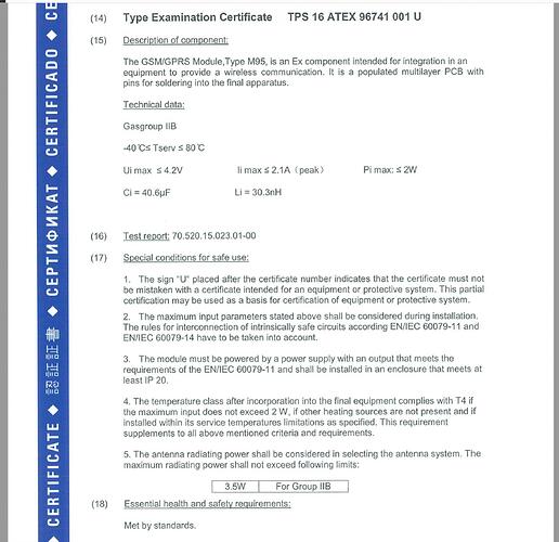
Here is ATEX certification of M95 GSM module:
As you see in the file, it’s mentioned: Ui(max)=<4.2V, Ii(max)=2.1A, Pi(max) =<2W.
As i know, i have to make a power supply which has limited parameters compatible with M95 Module values, means:
Uo(max) <4.2V, Isc(max)<2.1A, Po(max) <2W to keep the M95 Module in intrinsically safe state.
But current limiting is not possible by simply using a resistor, because in that case i need to use a 2ohm resistor which stops module working fine in normal conditions (because of high voltage drops result of pulse current sinking of GSM module - up to 1.6A )
So the only solution is using Active current and Active power limiters !
Is this right ?
another problem is that limiting Po to <2W seems not working, i.e i set voltage to 4V, then i have to set maximum current on 0.5A only to achieve max Po < 2W ! but 0.5A current is not enough to support high current sink pulses of the module (according to datasheet, it needs up to 1.6A current pulses). so in fact making a working circuit with power supply designed according to the parameters of the certification seems not possible …
Because of using device in Zone 1, i have to use 2 series of each Current and power limiters … which seems more strange !
Note that I just need the maximum antenna radiation of the module to stay lower than 3.5W, Because i want to use whole GSM circuit and module in an encapsulation according to ATEX, but the antenna will be out of encapsulation, so antenna radiation should be still limited down to <3.5W to be compatible for gas group IIB.
Do you have any suggestion helping how to solve this matter ?
Thanks
