Hi everybody!
First of all, this is my first post in this Quectel forum. Second, I want to apologize for my English, it is not my mother tongue.
I’m working with my new Quectel BG96 and I’ve a big issue, I do not understand what the bg96 response me. The first thing I thought that the problem would be the baud rate. I’m working with my Arduino UNO and programming on the Arduino’s IDE, in Arduino specifications say that the Serial ought to work with 9600 baud and the default bg96 baud rate is 115200 baud. After trying different baud rates and discuss the same problem in the Arduino Forum, I’ve decided to print the AT command’s replies with my SSD1306, but the result was the same, unintelligible symbols in some command’s replies.
I want to show us the last bg96 response:
Welcome to use NB-IoT Shield QG96
�
ATI
��ect�l
BG96
Rewision: �G9fMAR02A07M1G
OK
AT+G�N �
8651704546509b OK � AT+�FUN=a OK � AT[QCCID +QC�ID: 89r40??1eghr0528241F
��
�
AT[COPS=`
�K
�
AT+ASQ +CSQ: 89,99
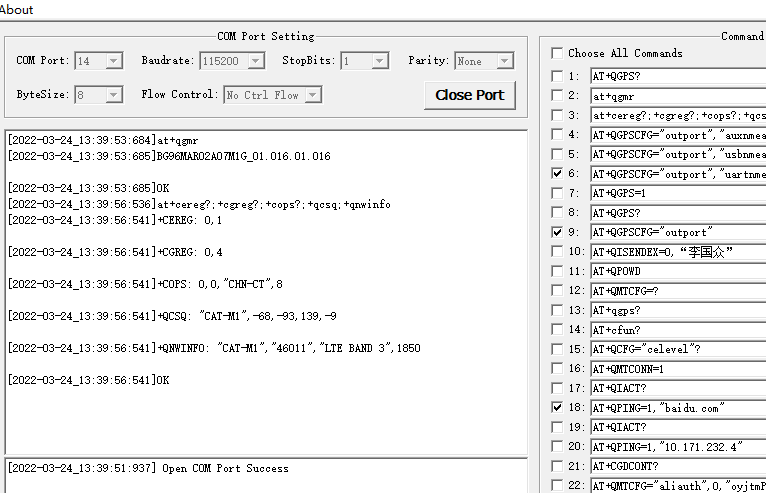
Searching on this forum I’ve found that the problem would be the fw of my bg96. Using the commands ATI and AT+QGMR I find the Revision number of my bg96
Revision: BG96MAR02A07M1G_01.017.01.017
The purpose of my project is measuring RSSI level when you’re walking around the street. I said this because I read that the R02 version would be problematic with Handovers
If somebody knows how to solve this issue, please tell me how
PD: I include the code that I wrote whether it would help
#include <SoftwareSerial.h>
#include <ATcommands.h>
#include <Arduino.h>
#include <SPI.h>
#include <Wire.h>
#include <Adafruit_GFX.h>
#include <Adafruit_SSD1306.h>

#define RST 4 // Reset PIN module
#define UART_RX 10 // Serial PIN RX connection
#define UART_TX 11 // Serial PIN TX connection
#define WIDTH_DISPLAY 128 // ancho pantalla OLED
#define HEIGTH_DISPLAY 32 // alto pantalla OLED

SoftwareSerial mySerial(UART_RX, UART_TX);
Adafruit_SSD1306 screen(WIDTH_DISPLAY, HEIGTH_DISPLAY, &Wire);
//ATcommands module = ATcommands(RST,false);

const char* IP = "IP";
const char* APN = "m2m.movistar.es";

void setup() {
  Serial.begin(9600);
  mySerial.begin(115200);
  //module.begin(mySerial);
  while (!Serial) {}
  //Serial.println("Welcome to use NB-IoT Shield QG96");

  ATresponse("ATI", 1000);
  ATresponse("AT+GSN", 1000);
  ATresponse("AT+QSIMDET=1,0", 1000);
  ATresponse("AT+CFUN=1", 1000);
  ATresponse("AT+QCCID", 1000);
  ATresponse("AT+COPS=0", 1000);
  ATresponse("AT+CSQ", 1000);
  ATresponse("AT+COPS?", 1000);
  ATresponse("AT+CGDCONT=1,IP,APN", 1000);
  ATresponse("AT+CGATT=1", 1000);
  ATresponse("AT+CGDCONT?", 1000);
  ATresponse("AT+CGACT=1,1", 1000);
  ATresponse("AT+CGPADDR=1", 1000);
}

void loop() {
  updateSerial();
}

void ATresponse(String AT, int wait){
  // The function extract the AT command response and specified
  // a delay between different commands
  mySerial.flush();
  delay(wait);
  mySerial.println(AT+"\r\n");
  updateSerial();
  char ATresponse[200];
  for(int i = 0 ; i < 200 && mySerial.available()>0 ; i++){
    ATresponse[i++] = mySerial.read();
  }
  //Serial.println(Atresponse);
  String ATreturn = String(ATresponse);
  display(ATreturn);
}

void updateSerial(){
  while (mySerial.available()) {
    Serial.write(mySerial.read()); //Forward what Serial received to Software Serial Port
  }
  while (Serial.available()) {
    mySerial.write(Serial.read()); //Forward what Software Serial received to Serial Port
  }
}

void display(String response){
  screen.begin(SSD1306_SWITCHCAPVCC, 0x3C);
  screen.clearDisplay();
  screen.setTextColor(SSD1306_WHITE);
  screen.setTextSize(2,2);
  screen.setCursor(0, 0);
  screen.println(response);
  screen.display();
}
