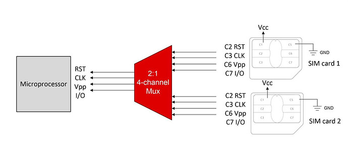
Currently, my BG95 module works. It can power the sim card and send/receive messages with one sim connector. I want to use TXS02326A to multiplex it so I can switch between two sim cards. The issue is the BG95 drives the USIM_VDD pin. It briefly powers up to 1.8v and turns off if a sim isn’t detected. So I have several questions regarding the how the USIM_VDD pin works.
- What triggers the USIM_VDD pin and how do I keep it on?
- Can I connect USIM_VDD to the mux chip (TXS02326A) 1.8v LDO and power on at all times? Is it safe to power the USIM_VDD to 1.8v at all times?
- Or can I connect the USIM_VDD pin from the BG95 directly to both sim connectors and let the mux handle only the signals (IO/DATA, CLK, RST)?
Please let me know what I can safely do to mux between two sims.
Here’s the diagram, but the microprocessor (BG95) has a USIM_VDD that powers the sim. What should I do with the USIM_VDD? And how do I prevent feedback coming from the sim if one sim will be powered and the other one will be switched on?
