I have some question related to the BG95-M3 with LGA footprint.
Is the PWRKEY pin the only way to turn on the modem?
If I supplying VBAT_BB, what happens next? is the module waiting for a trigger from the PWRKEY pin to activate the internal system processor and the module itself?
If the PWRKEY pin is the only way to turn on the modem, what kind of circuit to trigger that pin without push button or external MCU by following timing of powering module diagram itself?
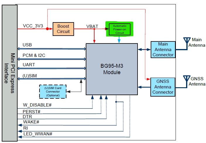
On BG95-M3 Mini PCIe functional diagram, I see there is a circuit that might help answer my question, the block I marked with green on below picture.
PWRKEY pin is the only way to turn on the module. You can also use RESET pin if you want. Those two pins are connected inside the module.
If VBAT_BB is applied, the module would wait for the PWRKEY to be grounded to initiate the power-on sequence from the master PMIC device.
The automatic power-on circuit is used to turn on the module. Yes, it is the one in question4. The PWRKEY is connected to the collector terminal of a BJT and VBAT_BB is connected to the base terminal through capacitors. When we supply VBAT_BB, the PWRKEY is high at first, and then transition from high to low. Then the module is turned on automatically.
Both EG25 Mini Pcie and EG21 Mini pcie functional diagrams lacks the automatic power on circuit shown on the BG95-M3 Mini PCIe functional diagram.
So I have similar questions for EG25 and EG21 minipcie
Is the PWRKEY pin the only way to turn on the EG21 and EG25 modems?
If I supplying VBAT_BB, what happens next? are the module waiting for a trigger from the PWRKEY pin to activate the internal system processor and the module itself?
If the PWRKEY pin is the only way to turn on the modem, what kind of circuit to trigger that pin without push button or external MCU by following timing of powering module diagram itself?
Do EG21 and EG25 mini pcie have an auto circuit like the one mentionned above ?