Hello ,
I’m testing the BC68. In the datasheet , the max power is 23dBm.
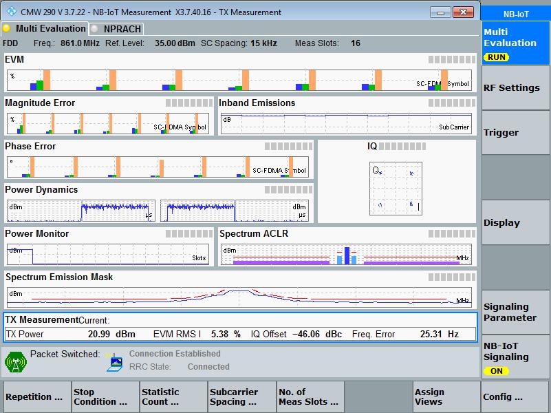
When i do the test (on a CMW290) , i find 21 dBm. This is the maximum power i find , either on my PCB , or on the evalboard.
How many connectors do you have from the PCB with the module BC68 to the CMW290 Functional Radio Communication Tester?
On the one hand, you should have to check the losses from the connectors, they are usually around 0.2-0.3dB.
And on the other hand, you should have to check the impedance of the track from the BC68 to the UF.L or SMA connector, the track has to be 50 Ohms. Probably there is a matched filter for adapting the antenna, and for making proper measurements you should have to remove the matched filter and place 0R resistors.
I am not completely sure, but I think with NB-IoT, the output power is regulated automatically and it depends on ECL parameter (Enhanced Coverage Level). So I don’t know if you are going to be able to see 23dBm in the output.
The BC66 module should have a Continuous Wave mode (Power without any kind of modulation) or something similar, like other communication modules like Sigfox, in order to check the maximum output power and with the main goal to get a 3D radiation diagram.
I am sure that for this purpose there is an engineer command, but this kind of commands are only for internal use. But I think you can ask for this to Quectel. They should give us this kind of commands. I think is the only way to get a 3D radiation diagram of your final product.
Hi Ahjaouadi
The maximum value of TX_POWER is 23dbm, but in actual applications, the maximum value is 23dbm unless the network environment is very poor.
The AT command can be used to force the module to a maximum of 23dbm, which is not recommended.
Ok, I thought it was in the manual related to AT commands.
Do you know if there is an AT command to put the module in a continuous wave mode in order to get the 3D radiation pattern? I am not asking the command only if there is a commando or this purpose. It will be very useful.
Hi Oscargomezf
There is no AT commands. This is an internal command and is documented separately. Generally not open to the outside world.
You can contact your local Quectel FAE to obtain it.