BC66 GPIO pins and Dallas Semi temperature sensor

Dear Quactel forum,

Thank you for all nice question&answers on the forum. Forum is really helpful.

I will ask on behalf of our school and research team a few questions regarding Quactel BC66 chip general purpose I/O pins (GPIOs). Development environment is Platform IO and we are using OpenCPU libraries.

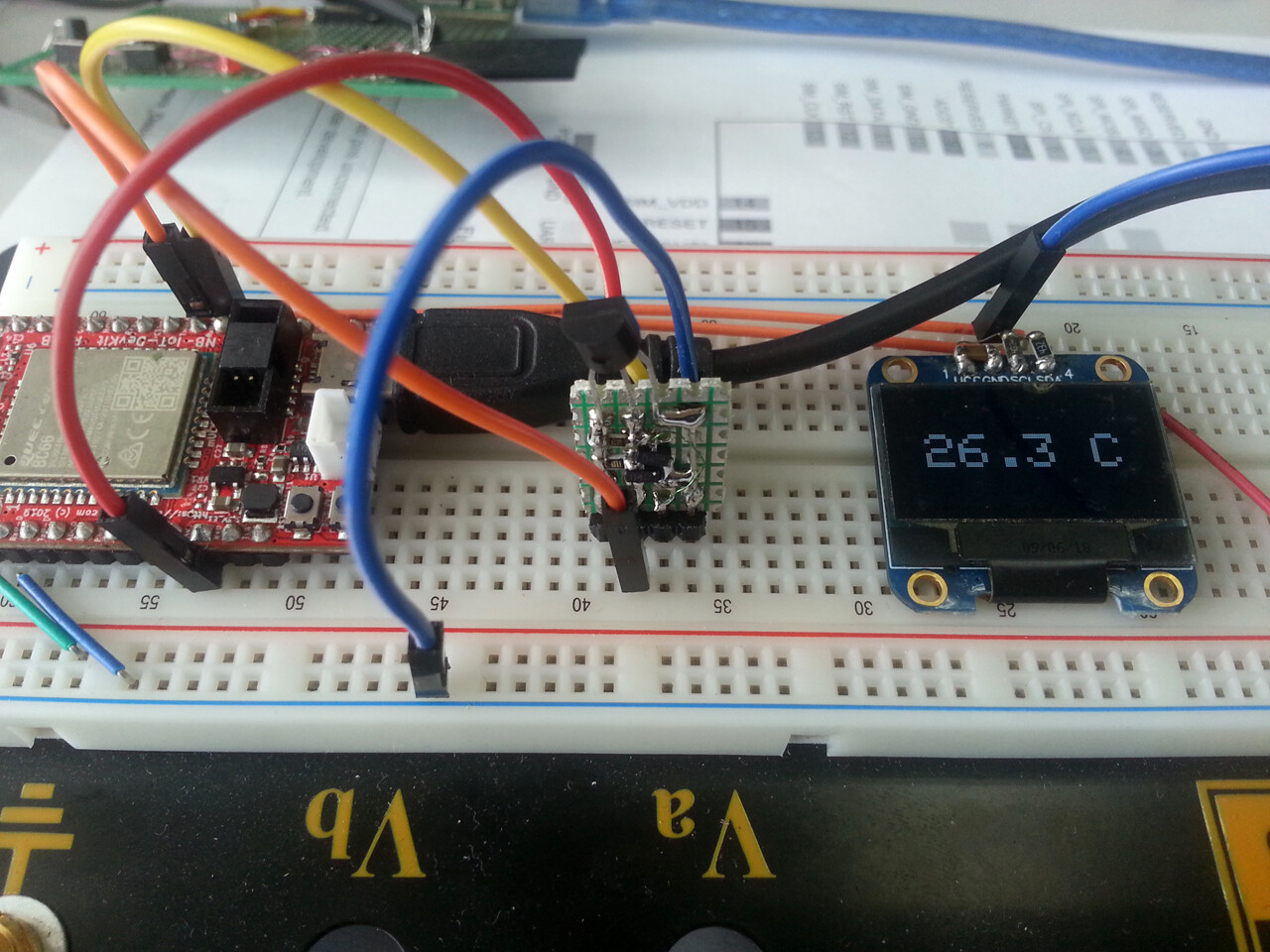
We have try to connect Dallas Semicoductor DS18B20 temperature sensor directly to the GPIO pins. We have managed to toggle GPIOs with simple on and off code. And it seems to work with blinking LED (and measured with volt meter). However, we have recognise that the GPIO signal is not stabile. It’s switching randomly even we do nothing. This inconvenience makes errors between CPU and temperature sensor and readings are random.

We have tried switch off all power savings / sleep modes. We have also tried example: (https://github.com/Wiz-IO/platformio-quectel-examples/blob/master/BC66_SDK/OpenCPU/example_gpio.c) which works fine.

Temperature sensor circuit works on Arduino development board. So, all connections are done properly and there are 4,7kOhm resistor.

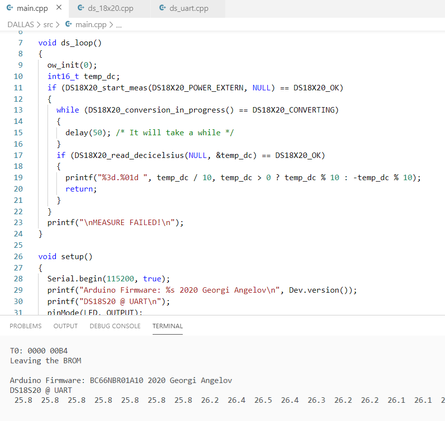
Please, see below the simple sample code where we just toggle GPIO pin which is used to reset temperature sensor.

Questions:

  1. Is this behaviour something that someone other has recognised?
  2. Any suggestions how to setup correctly the pins and how to avoid this kind of random switching?
  3. For OpenGPU is there similar Arduino functions available as pinMode(), digitalRead() and digitalWrite()?
  4. Is there available official library for Dallas temperature sensors on BC66 environment? (we have used our own tweaked from Arduino library)

Example code:

See the simplified version of the code we are trying to use. The ow_reset() function is copied from the datasheet (https://pdfserv.maximintegrated.com/en/an/AN162.pdf) with “DQ” lines replaced with functions found in ql_gpio.h (original datasheet lines in /* */ comments). The circuit is as shown in https://create.arduino.cc/projecthub/TheGadgetBoy/ds18b20-digital-temperature-sensor-and-arduino-9cc806 with data pin connected to GPIO1/P26 pin on the olimex dev board. The power for olimex is provided using the USB-connector (laptop PC).

void proc_main_task(s32 taskId) {

/* UART register & open, timer register … */

Ql_SleepDisable();
Ql_GPIO_Init(PINNAME_GPIO1, PINDIRECTION_OUT, PINLEVEL_LOW, PINPULLSEL_PULLUP); // can be PINDIRECTION_IN, PINLEVEL_HIGH, PINPULLSEL_DOWN, etc… does not seem to matter much in practice
Ql_Timer_Start(TIMER_ID_USER_START + 2, 5000, TRUE); // timer that calls a callback function, which currently only calls ow_reset()
while(true){Ql_OS_GetMessage(&msg);} // loop calling Ql_OS_GetMessage( … )
}

static unsigned char ow_reset(void)
{
unsigned char presence;
Ql_GPIO_SetDirection(PINNAME_GPIO1, PINDIRECTION_OUT);

/* DQ = 0;	//pull DQ line low	*/
Ql_GPIO_SetLevel(PINNAME_GPIO1, PINLEVEL_LOW);

/* delay(29);	// leave it low for 480us	*/
Ql_Delay_us(480);

/* DQ = 1;	// allow line to return high	*/
Ql_GPIO_SetDirection(PINNAME_GPIO1, PINDIRECTION_IN);

// Ql_Delay_us(30); APP_DEBUG("%d\n", Ql_GPIO_GetLevel(PINNAME_GPIO1)); // wait 30us to see what happens. In general, returns 1, but also randomly 0

/* delay(3);	// wait for presence	*/
Ql_Delay_us(72);

/* presence = DQ;	// get presence signal	*/
presence = Ql_GPIO_GetLevel(PINNAME_GPIO1);
APP_DEBUG("Presence was %d\n", presence);	// sometimes this is not 0 for unknown reasons

/* delay(25); // wait for end of timeslot	*/
Ql_Delay_us(448);

return (presence);	// presence signal returned

} // 0=presence, 1 = no part

1 Like

Hi
you can not use read/write pin for Dalas sensor… read/write API is too slow

Here is Arduino pin functions ( based of OpenCPU API )

OpenCPU example

The best way for reading Dalas senseor is via uart ( module have 3 uarts )
example: https://www.maximintegrated.com/en/design/technical-documents/tutorials/2/214.html

Thank you WizIO! for pointing us to right direction. It was important to hear that only way is to use UART instead of GPIO pins directly. We made simple code to write/read based on this example: https://github.com/dword1511/onewire-over-uart

On the board we soldered two MOSFETs to act as a two way buffer as you proposed.
We first tried wrong UART (P17/P18) which was connected to USB serial line and it was generating a lot of errors as in this port there was a lot of traffic. So, we moved to other two UARTs (Pins P38/P39 (UART_PORT2) or P28/P29 (UART_PORT1)) and it seems to work better, but not quite error free. Following code produces bus errors; sometimes “ok” data which represents crap serial number 3-40 times; or “no devices found”. We are close but something is still wrong…

Code:

#include “custom_feature_def.h”
#include “ql_type.h”
#include “ql_stdlib.h”
#include “ql_uart.h”
#include “ril.h”
#include <stdint.h>
#include <stddef.h>
#include “ql_gpio.h”
#include “ql_error.h”
#include “ql_timer.h”
#include “ql_power.h”

#include “onewire-over-uart/onewire.h”

#define DEBUG_PORT UART_PORT0
#define DBG_BUF_LEN 512
static char DBG_BUFFER[DBG_BUF_LEN];
#define APP_DEBUG(FORMAT, …)
{
Ql_memset(DBG_BUFFER, 0, DBG_BUF_LEN);
Ql_sprintf(DBG_BUFFER, FORMAT, ##VA_ARGS);
if (UART_PORT2 == (DEBUG_PORT))
{
Ql_Debug_Trace(DBG_BUFFER);
}
else
{
Ql_UART_Write((Enum_SerialPort)(DEBUG_PORT), (u8 *)(DBG_BUFFER), Ql_strlen((const char *)(DBG_BUFFER)));
}
}

void uart_debug_callback(Enum_SerialPort port, Enum_UARTEventType msg, bool level, void *customizedPara)
{
APP_DEBUG(“uart debug callback called, status: %d\n”, msg);
// flash_led(0);
}

#define UART_PORT UART_PORT1
uint8_t id[OW_ROMCODE_SIZE];

static void temperature_timer_callback(u32 timerId, void *param)
{
APP_DEBUG(“temperature callback\n”);
if (ow_init(UART_PORT))
{
APP_DEBUG(“Bus INIT failed. Check COM port.\n”);
return;
}

// APP_DEBUG(“ow_reset: %d\n”, ow_reset());

uint8_t c = 0, diff = OW_SEARCH_FIRST;

while (diff != OW_LAST_DEVICE)
{
	diff = ow_rom_search(diff, id);
	if (diff == OW_ERR_PRESENCE)
	{
		APP_DEBUG("All devices are offline now.\n");
		ow_finit();
		return;
	}
	if (diff == OW_ERR_DATA)
	{
		APP_DEBUG("Bus error.\n");
		ow_finit();
		return;
	}
	APP_DEBUG("Bus ds Device %03u Type 0x%02hx ID %02hx%02hx%02hx%02hx%02hx%02hx CRC 0x%02hx\n",
		   UART_PORT, c, id[0], id[6], id[5], id[4], id[3], id[2], id[1], id[7]);
	c++;
}
APP_DEBUG("Bus listed.\n");

ow_finit();

}

void proc_main_task(s32 taskId)
{
s32 ret;
ST_MSG msg;
Ql_UART_Register(DEBUG_PORT, uart_debug_callback, NULL);
Ql_UART_Open(DEBUG_PORT, 115200, FC_NONE);
APP_DEBUG("[APP] Begin\n");

Ql_SleepDisable();

Ql_Timer_Register(TIMER_ID_USER_START + 2, temperature_timer_callback, NULL);

Ql_Timer_Start(TIMER_ID_USER_START + 2, 2000, FALSE);

while (1)
{
    Ql_OS_GetMessage(&msg);
    switch (msg.message)
    {
    case MSG_ID_RIL_READY:
        Ql_RIL_Initialize();
        APP_DEBUG("[APP] Ril Ready\n");
        break;
    }
}

}

I did a hardware staging but I don’t have time to try…
maybe the problem is: need fast swithcing uart speed 9600/115200
will test a hack: direct writing to uart brg register … but for now I not have time

some hints :slight_smile:
open uart at 9600 and 115200 and look difference for this registers

make your functions
set_brg_lo() { … }
set_brg_hi() { … }

Great, thanks! Will try these.

1 Like

Great! We are still struggling with low level. Any chance to have those library examples?

Thanks,

Jarkko

We understand now this as:

9600 baud = 9600 bit/s => 1/9600 s/bit ~100us/bit

Reset datasheet mentioned: (https://pdfserv.maximintegrated.com/en/an/AN162.pdf):

480us (minimum, low) + 15-60us pullup (high) + 60-240us presence (low)

Similar reset from maximin website:

https://www.maximintegrated.com/en/design/technical-documents/tutorials/2/214.html:

TX: 0xF0, would be 11110000 which is actually 0 0000 1111 1 (as start+stop bit, least-significant bit first)

115200/9600 baud = 12 times, so 12 x 115200 baud bytes means one 9600 baud byte.

11110000 using 9600 baud = 6 * 0xFF (11111111) + 6 * 0x00 (00000000) is using 115200 baud.

But, how about start + stop bitit, other words after every 8 bit FF (“high”) and 00 (“low”) will cut it with 0/1 bit (start/stop). This may cause problems with Dallas sensor.

We assume that start/stop bits cannot be disable from bc66/opencpu API.

Is that the reason why you proposed using 9600 baud reset?

Thanks,

Jarkko

Replying to my own question. Dallas might not recognise short stop/start bits at all if we operate 115200 bauds. I.e. one byte with 115200 bauds are interpreted as a one bit for Dallas and as it is level sensitive. Correct?

:slight_smile:
https://pbs.twimg.com/media/EZh7iu9WAAUjG9j?format=jpg&name=large

you can convert code for OpenCPU

Great! Thank you. :+1:

Do not search sensor IDs - too may time and watchdog reset module

Hello Wiz,

i’m trying to compile your code but all .h files are missing, can you provide ds_uart.h, ds_onewire.h, ds_18x20.h, ds_common.h? (i have tried to create headers with defined functions but its seems that i’m missing somethind :smiley: .

anyway what pins are you using for this example on test board from picture (Olimax NB-Iot DevKit - i have same board):

  • vcc - 3
  • gnd - 4
  • rx - ?
  • tx - ?

tnx!

@WizIO tnx!

i’ve tried to compile app but i have an error:

src/dallas.h:141:3: error: conflicting declaration ‘typedef struct UART_REGISTER_T UART_REGISTER_T’
} UART_REGISTER_T;
*^~~~~~~~~~~~~~~*

I fixed it by excluding #include <dallas.h>, OWU ds and Adafruit TFT (which i dont need) - now it compiles and i have sucessfully uploaded program to board but now it loops forever in method uart_getc where it looks for Serial1.available().

My question is - can i use simplified version of sensor wiring with diode which i currently use ( https://github.com/dword1511/onewire-over-uart ) or mosfet version must be used?

( sensor is connected to this four pins on Olimex board: https://ibb.co/NnWLgvT )

Thanks!

Arduino or OpenCPU?

just remove display code
Serial is used for console
Serial1 is sensor

B66 pins is 1.8v - “diode” cannot support levels and power for sensor - need ~1mA
use transistor schematic - I test with bipolar digital npn

@WizIO tnx, i need to buy NPN and test with it.

Anyway can Arduino Adafruit library https://github.com/adafruit/DHT-sensor-library can be used with DHT22 and BC66 ? I’m also having problem with it :smiley:.

tnx.

The GPIO API is too slow for DHT protocol… use smart sensors on SPI, I2C, UART

Hi All, please check this repository: https://github.com/visuallabel/DS18x20-uart-opencpu

We made porting to OpenCPU and this now works. Unfortunately, it still corrupt reading most of the time. There must be some glitch in the timing or then electronics needs some tuning. Can someone try this out and check whether the problem is in electronics or in code?

Thanks,

Jarkko and Tampere University team in city of Pori, Finland.