1、Is it normal that we can get response from UART after BC28 enter PSM or how can we know that BC28 had already enter PSM from URAT or states of the pin?
2、BC28JA-02-STD Revision:BC28JAR01A11
When the module enters PSM state, you can not get response from UART-USB on your PC. If you want to confirm the state of PSM, then send AT+CPSMS? with DTR selected.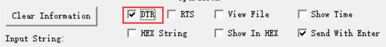
tahnk you frankfeng2020!
I’ve been told that BC28 based on Hisilicon platform can only enters PSM state(light sleep) by FAE.
When the module enters PSM state, you can get response from UART.
When the module(not BC28) which support deep sleep mode,we can not get response from UART.
We can also confirm the state of module by AT command
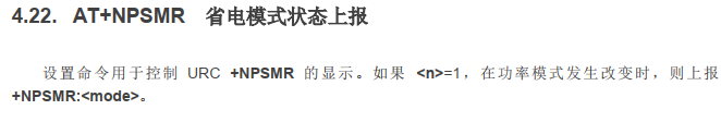
when the module enters PSM , we can get “+NPSMR:1” from UART.
hello,i got another question for you.
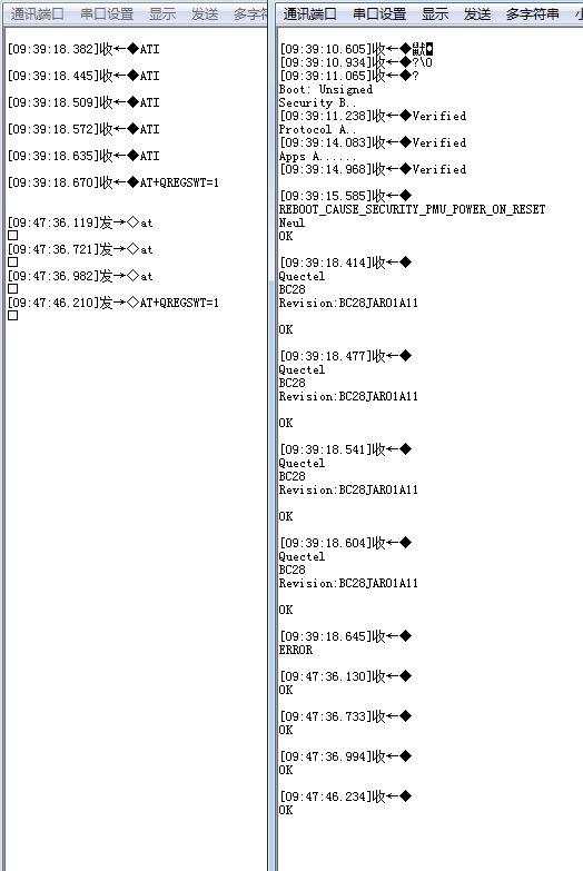
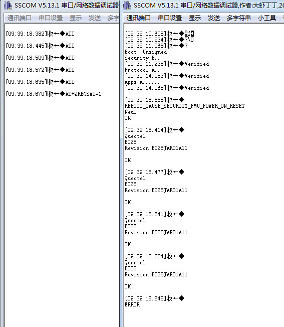
After BC28 Power on,i’ll send “ATI” command 100times. sometimes,BC28 won’t response ATI command and then don’t response any AT command.
MCU Module
ATI OK…
ATI OK…
ATI OK…
ATI No response
ATI No response
ATI No response
AT+CSQ No response
AT No response
When you want to enter PSM mode entirely,
first, AT+CFUN=0, keep the basic function and shutdown most of function.
second, AT+CPSMS=1, enter PSM mode. You can have a trial to see if the UART can get reponse.
AT+NPSMR was set once, then when the module got reponse from the communication base station, the module will be activated and sends the state by UART.
如果你想完全进入PSM,第一步先设置CFUN=0,第二步开启CPSMS进入PSM模式,海思平台不像高通平台有QSCLK这个轻度睡眠模式,像高通平台的话需要再加QSCLK=1然后才能PSM=1。你可以先试下CUN=1&CPSMS=1来看看能不能接收串口信息,记得关闭掉DTR。有DTR是可以激活到的。
如果用NPSMR的话(在PSM之前设置),当有基站激活模块的话,就会通过串口主动上报。
Maybe the module enter into PSM mode, pls confirm the state of module(CFUN=1? or PSM=1?), if the module enter into PSM, then it will not reponse.
可能你的模块进入了PSM模式,请确认下模块的状态。如果进入了PSM模式是不会响应的。
1 Like
谢谢 frankfeng2020
串口通讯异常的问题是这样的:
我会在2s内下发100次ATI指令,模组有时候会出现前面50次指令响应正常,第51次不响应ATI指令,而且其余所有指令都不识别了。正常情况下,对于100次ATI指令都会有回应,就判定串口通信正常,才会发送接下来的指令。这么短时间应该不能进入PSM状态,而且在未进入PSM状态下,下发指令,模组能进入PSM状态吗?
Hello luo,
只有等上一个AT指令返回答复之后才能发送下一个AT指令,这样才算是正常的。
如果上一个AT指令发送完毕但没有返回,马上发送下一个AT指令,会造成死机。在写代码时候需要注意。我认为2秒100次可能模块无法及时回复造成后续no reponse。
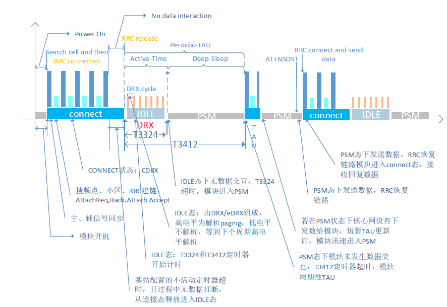
当模组执行最后一个动作进入idle空闲态时,且idle空闲态没有任何动作,idle之后就会进入PSM,不存在发着发着指令进入PSM这种情况。
Good information thanks for sharing
HP Field Support Engineer
Hello alex,
If you need the information or answer in Chinese, I will share the answer about this problem in English.
你好,frank
还是上次的问题,就是程序这边已经确定发完ATI,模组有响应之后才会继续发下一条ATI指令,但是还是会出现模组不响应指令的情况
frank,你的这个回答估计会让alex直接自闭
当他需要中文信息时,你会给他英文形式的回答
实际测试中还发现了一个奇怪的问题,我们使用MCU发指令,BC28的串口没有响应,但是使用USB转串口模组飞线到模组端,模组收发指令又是正常的
sorry,我看他贴上的超链接是外语网站,担心没看懂中文。另外我们有中文的论坛,https://forumschinese.quectel.com/
关于这个情况,请问是否有Log或者有展示的结果可以看到让我们分析?
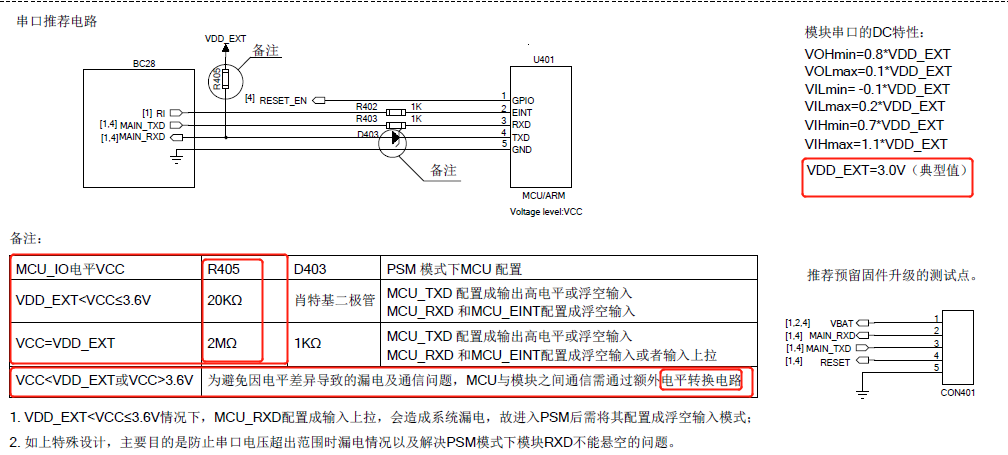
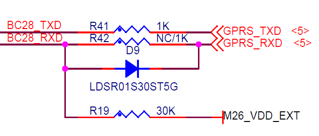
请确认一下原理图是否遵循以下的设计原则,有一些USB转串口工具为了提高抗干扰能力 会在信号上线内置上拉电阻,所以如果MCU串口发数据到BC28的话,具体确认一下
1.输出端(MCU)、输入端(BC28)的电平是否有变化;
2.输入端RX的高电平是否达到了VOHmin0.8*VDD_EXT=2.4V
1 Like
串口电路现在焊接的是D9,没有焊接R42,PCB板上两个器件位置是重合的,R19现在用的是30K,但是20K的我也试过;MCU的串口默认都是输入态(高阻),只有在与模组通信时才会切换到串口
串口没反应之后,我现在通过USB转TTL发指令,模组可以识别