I am trying to develop a device which might use the BG96 as the communication component. This device will also have an MCU which will communicate with the BG96 through the UART port.
From what I understand from its datasheet, and correct me if I am wrong, the BG96 has its main UART which communicate in the 1V8 range, which is perfect for me since my MCU also communicates with 1V8.
Therefore, I ordered the BG96 evaluation board and the UMTS & LTE EVB Kit. So far so good, I am able to connect it to the computer and communicate with the module.
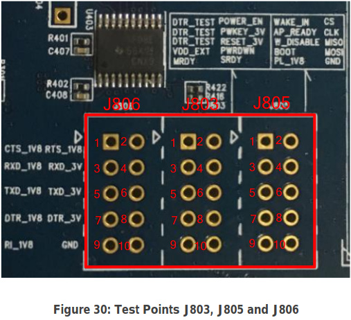
However I am not able to communicate with it in the 1V8 range. To do this, I am disconnecting the COM1 cable and connecting my own FTDI cable (1V8) to the pins 3, 5 and 10 on the J806 test points of the EVB Kit, which are RX, TX and GND according to the datasheet:
With this connection, I am able to receive commands but I am not able to send them to the module. My guess is that one of the ICs that convert the UART_1V8 to 5V for the COM1 port acts as another load and the signal can not be read by the BG96.
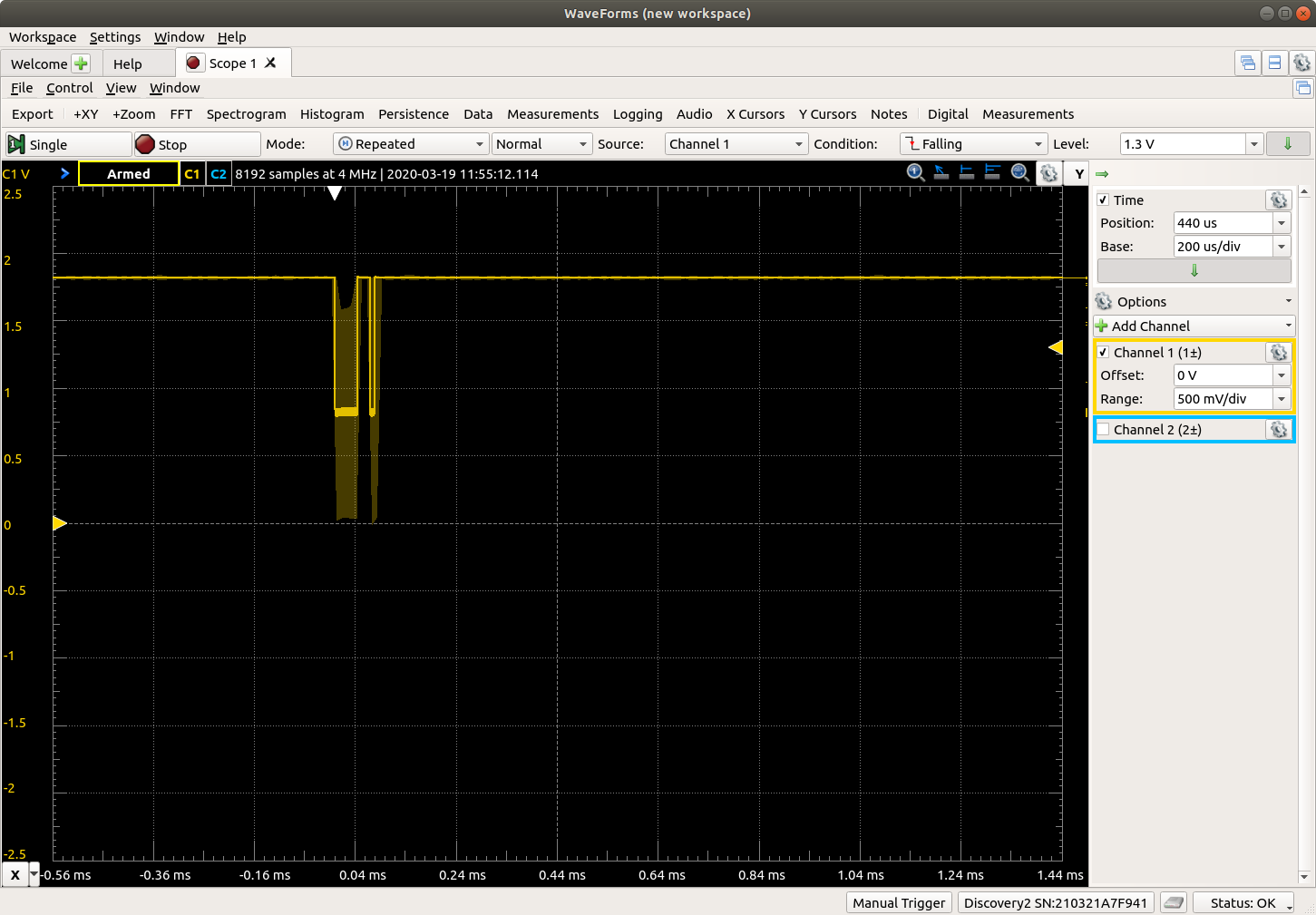
I connected a portable oscilloscope to these lines and saw that, when data is being communicated, the BG96 TX is able to go to 0V to communicate. But the FTDI TX (or BG96 RX) is not able to go to 0V, which seems odd.
So, this brings me some questions:
Is there any way to communicate with the module through an 1V8 UART using the EVB Kit?
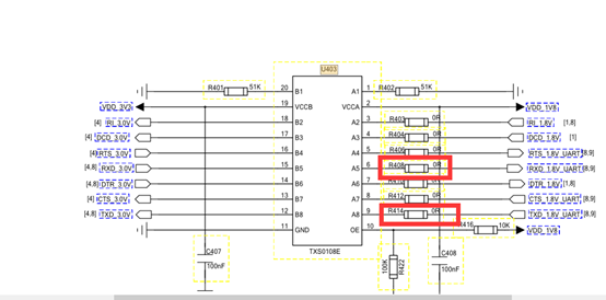
What causes this behaviour? Is it the U403 (TXS0108E) or the U401 (SN65C3238) ICs which are indeed acting as load?
Finally, would unsolder these ICs make the BG96 able to communicate directly with my MCU/ FTDI cable?
I would attach more images to better illustrate my problem but this forum does not allow me to.
It seems that the way of your connection is no problem . pls try to connect your 1.8 v Uart to BG96 with your PC first , sometime , This issue come from MCU’s clock .
2 you can connect your 1.8v TX/RX to BG96 directly and skip U403 &U401
I attached the sch of EVB as below for your reference .
As I already said in my post, I connected the BG96’s 1.8V UART to my computer first using a 1.8V TTL to USB FTDI cable. This problem occurs both with the cable and with the MCU.
How can I do that? I though doing so would be just connecting to J806. I checked the schematics and it just further validates my connection.
This is where I am making the connection (blue arrows):
In the end, I want to connect the BG96 1.8V UART to my MCU 1.8V UART, so there should be no need for a level converter. At the moment, as I said, I am using a 1.8V TTL to USB FTDI cable to debug first.